Object recognition system

a recognition system and object technology, applied in the field of object recognition system, can solve the problems of not being reliable, not suitable for rapid human face recognition, missing mask area, etc., and achieve the effect of reliable and easy recognition

Active Publication Date: 2008-07-22
PANASONIC SEMICON SOLUTIONS CO LTD
View PDF2 Cites 44 Cited by
  • Summary
  • Abstract
  • Description
  • Claims
  • Application Information

AI Technical Summary

Benefits of technology

[0005]In view of the above insufficiencies, the present invention has been accomplished to provide an object recognition system which is capable of determining the mask area from within a subject image [S] accurately and rapidly for reliable and easy recognition. The system in accordance with the present invention includes a template memory storing an image size template [T], an image reader taking the subject image [S] to be verified, and a mask locator which locates, from within the subject image [S], the mask area [M] corresponding to the image size template. The mask locator is designed to have an image converter, a feature analyzer, a table, a vote module, and a detection module.
[0013]The vote module may be configured to vary the distance (L) within a predetermined range in order to calculate a plurality of the candidates for each of the varied distances, and to make a vote on each of the candidates. The distance (L) is indicative of a size of the mask area [M] relative to the image size template [t]. In this instance, the detection module is configured to extract the varied distance from the candidate having a maximum number of the votes, thereby obtaining a size of the mask area [M] relative to the image size template M. Thus, even when the subject image [S] includes a target object which differs in size from the image size template [T], the mask locator can determine the relative size of the mask area [M] to the image size template [T], thereby extracting the mask [M] in exact correspondence to the image size template [T]. When the object recognition system is utilized in association with a security camera or an object verification device, the relative size of the mask area thus obtained can be utilized to zoom on the mask area for easy confirmation of the object or the human face or to make a detailed analysis on the mask for verification of the object. Therefore, when the object verification is made in comparison with a verification image template [V], the verification image template [V] can be easily matched with the mask area [M] based upon the relative size of the mask area.
[0015]Further, the vote module may be designed to vary the angle (α+φ) within a predetermined range in order to calculate a plurality of the candidates for each of the varied angles (α+φ), and make a vote on each of the candidates. In this instance, the detection module is designed to extract the varied angle (α+φ) from the candidate having a maximum number of the votes, thereby obtaining a rotation angle (φ) of the mask area [M] relative to the image size template [T] for matching the angle of the template with the mask area [M]. Thus, even when the subject image [S] includes an object or human face which is inclined or rotated relative to the image size template [T], the mask locator can extract the mask area [M] in correspondence to the image size template [T], and therefore give a relative rotation angle of the mask area to the image size template [T]. The relative rotation angle thus obtained can be therefore best utilized to control the associated camera to give an upright face image for easy confirmation, or to match the verification image template [V] with the mask area [M] for reliable object or human face verification.
[0018]Further, the detection module may be designed to include a like a selector for candidates having the number of votes exceeding a predetermined vote threshold, a like mask provider setting the mask area [M] around the center defined by each of selected candidates, and a background noise filter. The background noise filter is configured to obtain a parameter indicative of the number of the votes given to each of the pixels selected around the candidate, and filter out the mask area [M] having the parameter exceeding a predetermined parameter threshold. Thus, it is readily possible to cancel the background noise for reliable verification.
[0024]Further, in order to save memory data size for rapid calculation, the image converter may be configured to compress the density-gradient directional template image [DT] and the density-gradient directional subject image [DS] respectively into correspondingly reduced images. The compression is made by integrating two or more pixels in each of the standard images into a single pixel in each of the reduced image by referring to an edge image obtained for each of the image size template [T] and the subject image [S]. The edge image gives a differentiation strength for each pixel which is relied upon to determine which one of the adjacent pixels is a representative one. The representative pixel is utilized to select the density gradient directional value (θT, θS) from each of the directional template and subject images [DT, DS] as representing of the adjacent pixels and is assigned to a single sub-pixel in each of the reduced images such that the reduce image can be reduced in size for saving a memory area.
[0030]The verification unit may further include a controller which is responsible for selecting one of sub-divisions each included in the mask area [M] to cover a distinctive part of the subject image, limiting the mask area [M] to the selected sub-division, and calling for the judge. The controller is configured to select another of the sub-divisions and limit the mask area [M] thereto until the judge decides the verification or until all of the sub-divisions are selected. Thus, by assigning the sub-divisions to particular distinctive portions of the object, for example, eyes, nose, and mouth of the human face specific to the individuals, the verification can be done when any one of the sub-divisions is verified to be identical to that of the verification image, which can certainly reduce the time for verification, yet assuring reliable verification.

Problems solved by technology

However, with the use of such simple shape as the template, it is likely to miss the mask area and is therefore not reliable for extracting the true mask area to be validated.
Therefore, the scheme requires a large number of arithmetic operations in order to obtain the optimum parameters, i.e., the optimum ellipse in best match with the mask area to be validated, and is not suitable for rapid human face recognition.

Method used


Image

  • Object recognition system
  • Object recognition system
  • Object recognition system

Examples


Embodiment Construction

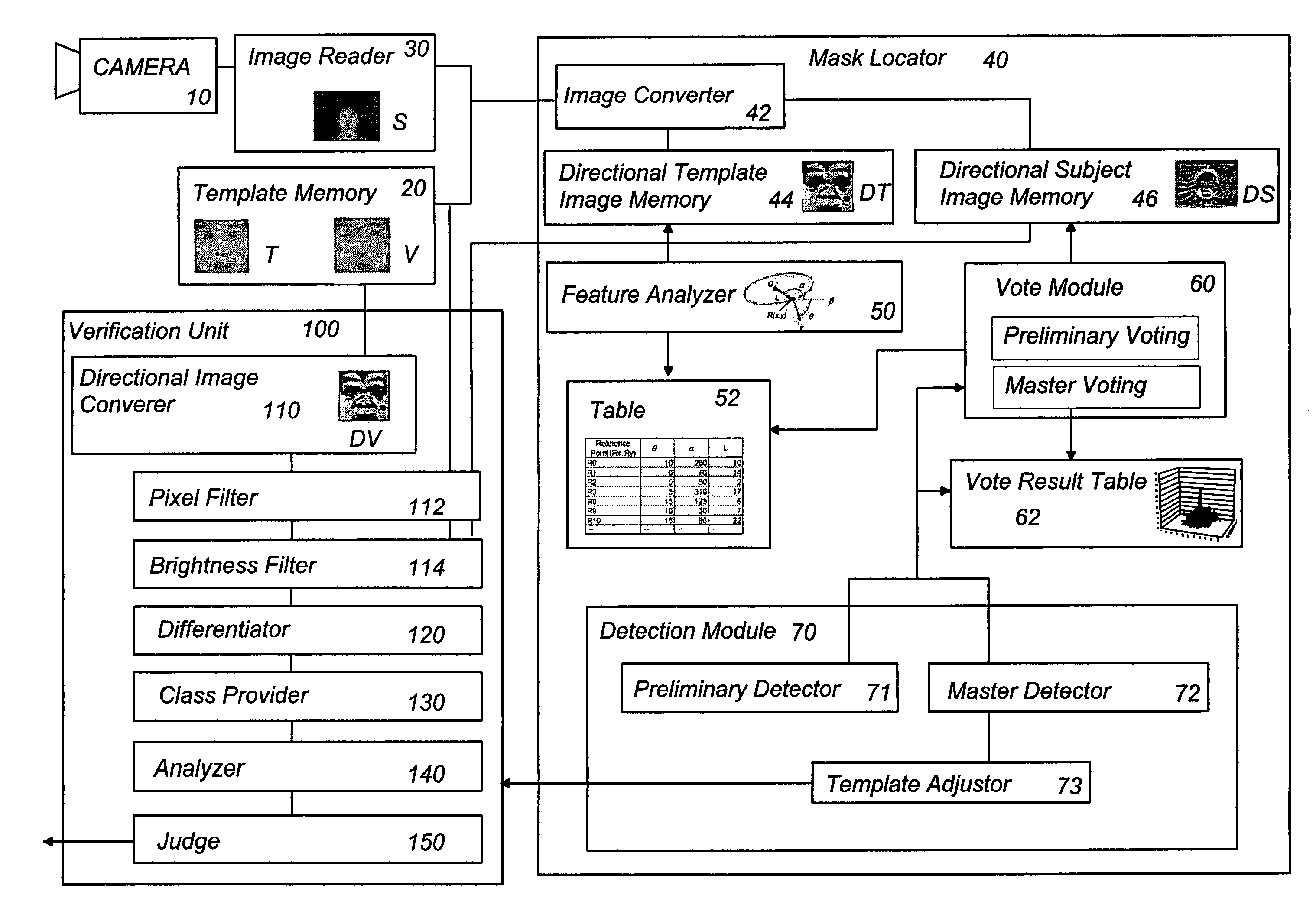
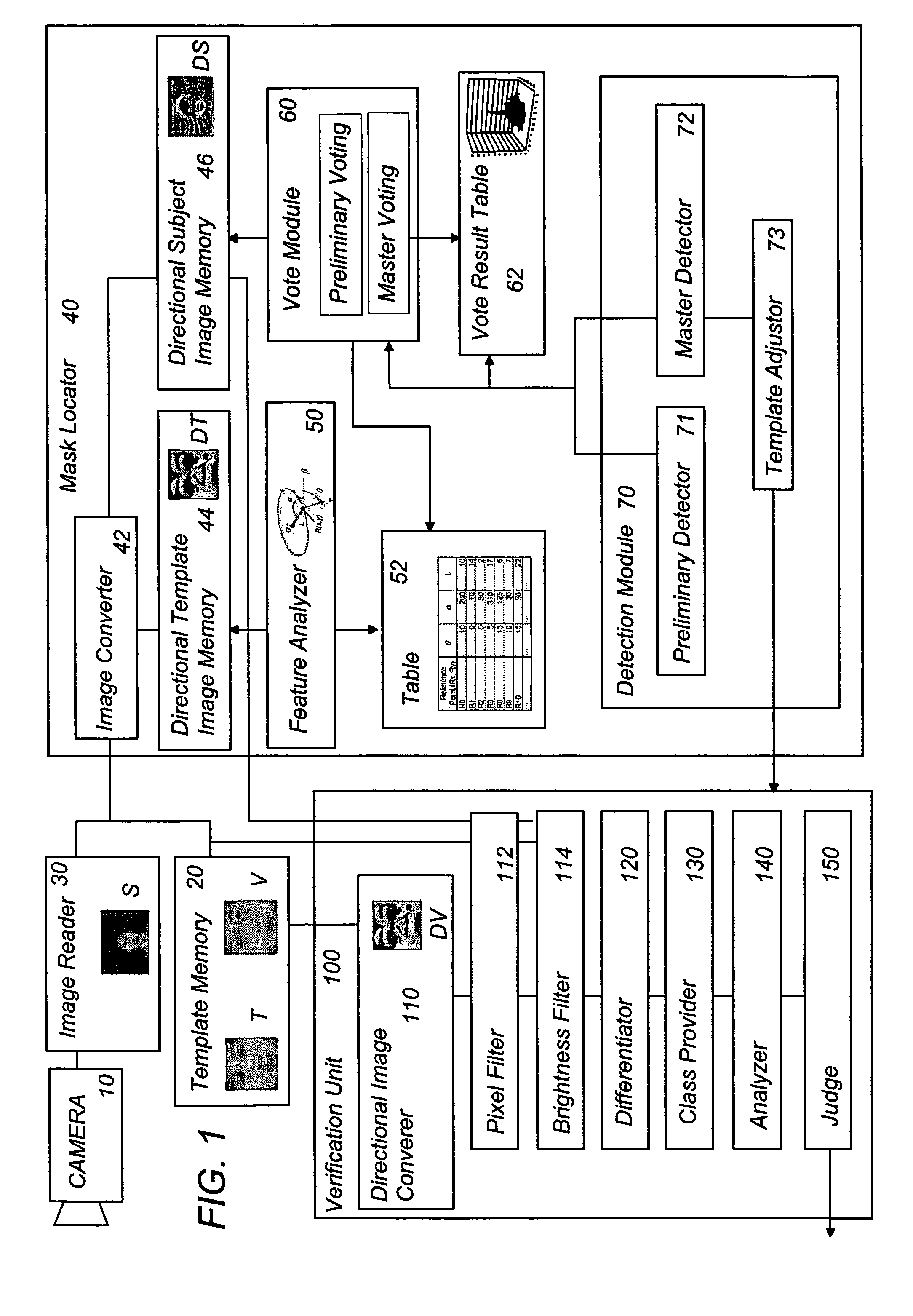
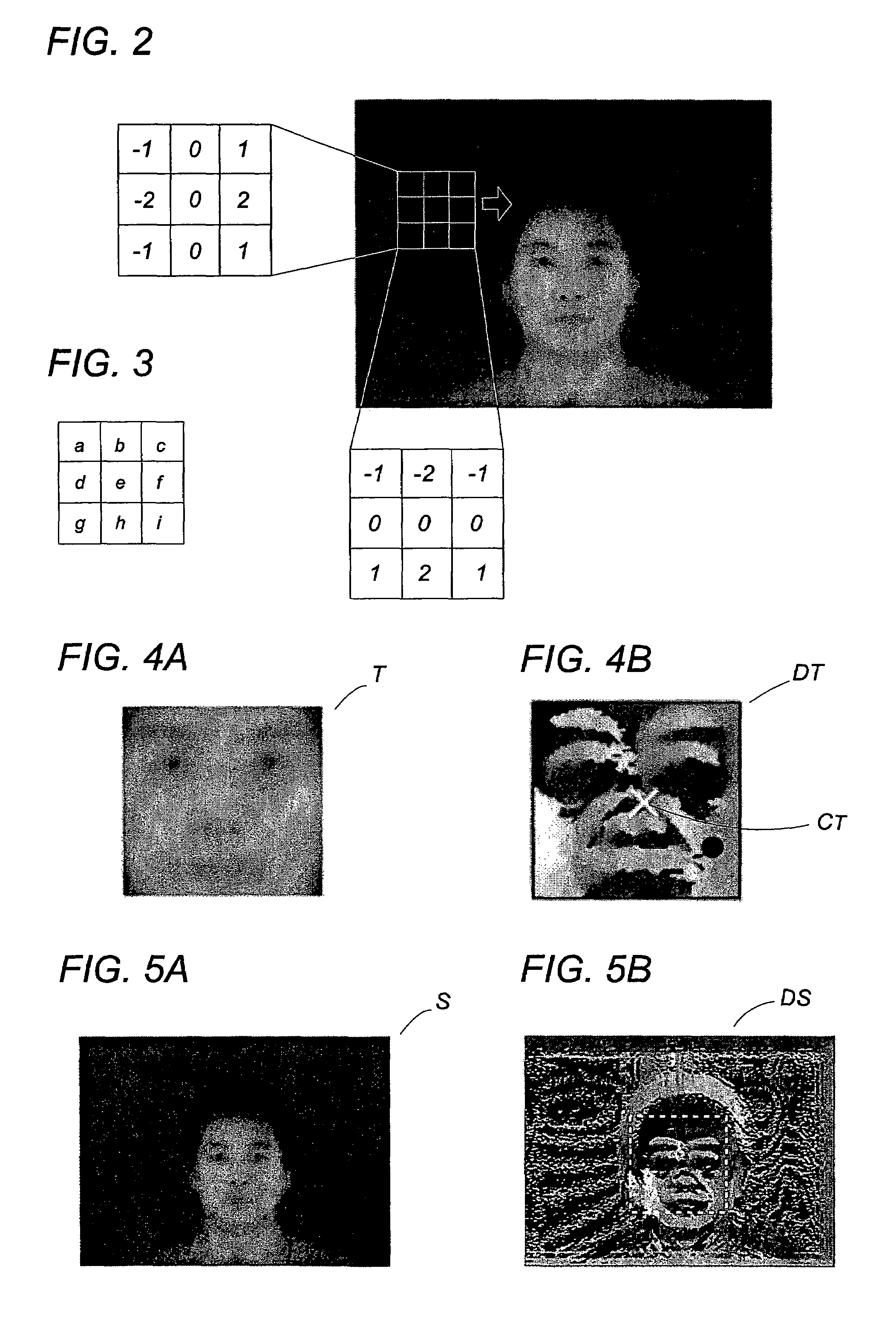
[0085]Referring now to FIG. 1, there is shown a human face recognition system in accordance with a first embodiment of the present invention. Although the illustrated embodiment discloses the system utilized for human face verification as one typical application, the present system is not limited thereto and can be equally utilized in combination with a security camera or the like camera for controlling the camera to zoom on the human face and / or make an angular adjustment, realizing easy confirmation of the human face in the subject image. In this sense, the system may be also incorporated in an image processing system which is designed to correct the human face image for easy and reliable identification of the human face. Further, it should be noted that the present invention should not be limited to the human face recognition, and could be equally utilized for recognition of any other object having peculiar image properties, for example, assembly parts running in a factory assemb...


PUM


Abstract

An object recognition system utilizes a mask locator for extracting a mask area (M) from within a subject image in order to recognize the mask area (M) with a subject image. The mask locator (40) refers to density gradient directional images respectively converted from an image size template and the subject image, and analyzes these density gradient directional images particularly with respect to the density gradient directional values (θT, θS) assigned to each pixel in each directional images to obtain parameters linking the image size template to the mask area (M) to be registered with the image size template. The mask locator has a vote module (60) which gives candidates for the center of the mask by varying the parameters and votes on the candidates. Based upon the number of votes for the candidates, a detection module (70) designate one of the candidates having a maximum vote number as the center of the mask area (M), thereby determining the mask area (M) around thus designated candidate within the subject image for exact recognition of the object in the subject image.

Description

TECHNICAL FIELD[0001]The present invention is directed to an object recognition system, and more particularly to a system effective for identifying the presence of a particular object or a human face in a subject image taken.BACKGROUND ART[0002]An object recognition requires to extract a particular mask area within a subject image in order to validate the mask area by comparison with an object image template. There have been proposed a scheme for extraction of the mask area, for example, as disclosed in US2001-002932 and JP09-73544.[0003]US2001-002932 discloses a human face image extraction system which selects a suitable template in order to extract the mask area from within the subject image that matches with the template. The template is selected to include a circular, ellipse, or polygon in anticipation of that the human face has a contour analogous with such simple shape. However, with the use of such simple shape as the template, it is likely to miss the mask area and is there...

Claims


Application Information

Patent Timeline
Patent Type & Authority Patents(United States)
IPC IPC(8): G06K9/00G06V10/50
CPCG06K9/6203G06K9/4642G06V10/50G06V10/7515
Inventor NAKAMOTO, EIJIHAGIO, KENICHIHIRONO, ATSUYUKIFURUKAWA, SATOSHI
Owner PANASONIC SEMICON SOLUTIONS CO LTD
Why Eureka
Try Eureka