Automatic faucet for lavatory unit of aircraft

a technology for aircraft lavatory units and faucets, applied in the direction of dispensers, light and heating devices, holders, etc., can solve the problems of unsanitary space between two equipments, inefficient faucet equipment, and inability to confirm the washing status easily

Inactive Publication Date: 2008-08-05
JAMCO
View PDF12 Cites 51 Cited by
  • Summary
  • Abstract
  • Description
  • Claims
  • Application Information

AI Technical Summary

Benefits of technology

[0014]Moreover, since the hand of the user is illuminated while the water or liquid soap is supplied, the user can confirm the washing status easily.
[0015]Further, the LED light indicating the water temperature enables the user to visually confirm the status of the water temperature.

Problems solved by technology

In a lavatory unit of an aircraft, it is inefficient to have a faucet equipment and a liquid soap dispenser disposed separately around the very small wash basin, and it is also unsanitary to have the two equipments spaced apart since the soapy water dripping from the user's hand makes a mess around the wash basin.
There is a faucet equipment and a liquid soap dispenser disposed around the very small wash basin, but they take up too much space on the already incapacious wash stand, are not very user-friendly, and block the user's view from confirming the washing status of the hands.
Further, since the prior art faucet is difficult to clean up, it may not be possible to ensure a sanitary condition.
Even further, since according to the prior art faucet the water temperature is difficult to confirm, the user may be injured by the hot water supplied through the faucet if the prior user of the lavatory has set the temperature too high.
Moreover, since there are a number of protruded objects disposed around the washbasin, when the aircraft receives impact due to turbulence or the like, which occurs quite often during normal flight of the aircraft, the passenger using the faucet may smash his / her hands or face suddenly against the faucet and be injured.

Method used


Image

  • Automatic faucet for lavatory unit of aircraft
  • Automatic faucet for lavatory unit of aircraft
  • Automatic faucet for lavatory unit of aircraft

Examples


Embodiment Construction

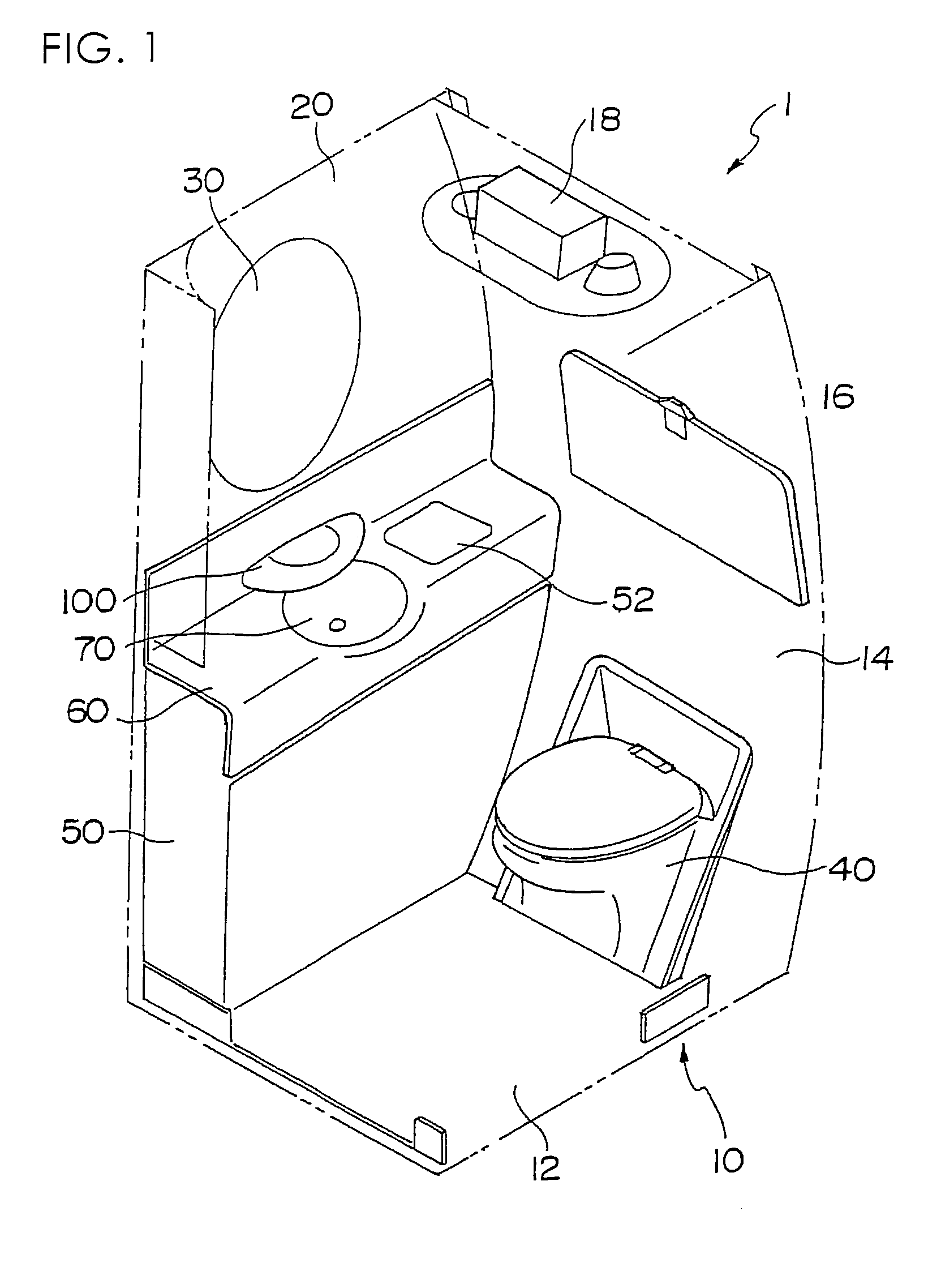
[0021]FIG. 1 is an explanatory view showing the general structure of a lavatory unit of an aircraft to which the present invention is applied.

[0022]The lavatory unit denoted as a whole by reference number 1 has a lavatory body 10 formed for example of honeycomb panels.

[0023]The lavatory body 10 is formed of a bottom panel 12, a side panel 14 and the like, and has a retractable table 16 and an illumination device 18.

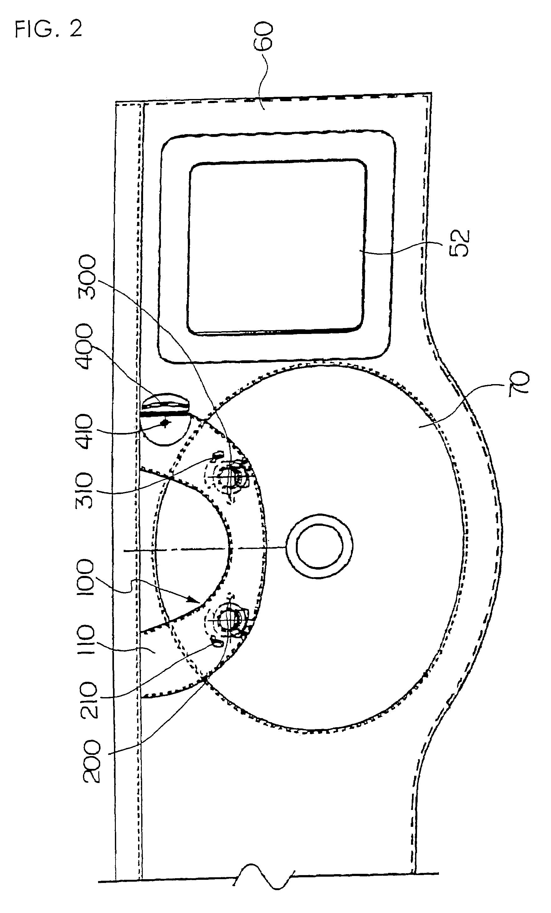
[0024]A lavatory bowl 40 and a housing 50 storing a dust box and the like are disposed inside the lavatory body 10. A wash stand 60 is provided on the upper portion of the casing 50, and a wash basin 70 is disposed at the center of the wash stand 60.

[0025]A door 52 through which trash is thrown in is attached to the upper surface of the wash stand 60.

[0026]A mirror 30 is attached to a wall panel 20 in front of the wash stand 60.

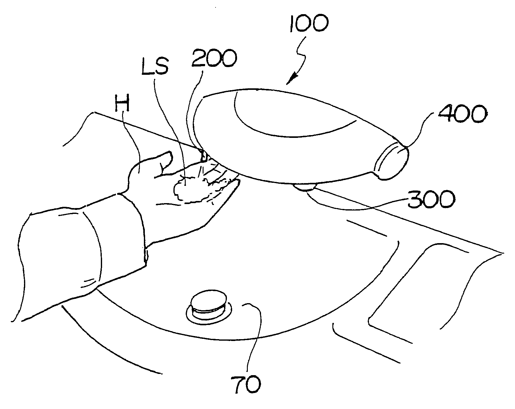
[0027]The automatic faucet 100 for a lavatory unit of an aircraft according to the present invention is disposed on an upper portion of a wash bas...


PUM


Abstract

The invention provides an improved automatic faucet for a lavatory unit of an aircraft. A body 110 of an automatic faucet 100 has on its lower left side (seen from the front) a liquid soap dispenser outlet 200, and the dispenser outlet 200 is connected to a liquid soap dispenser tank via a valve not shown. A reflective infrared sensor 210 for the liquid soap dispenser outlet and an LED light 230 for the liquid soap dispenser outlet are provided adjacent to the liquid soap dispenser outlet 200. When a user's hand is placed within the area of infrared waves 220, a predetermined amount of liquid soap is supplied over the user's hand. The LED light 230 is turned on to illuminate the user's hand. A water supply outlet 300 is provided at the lower right side of the body 110, which is connected to a water tank via a valve not shown. A reflective infrared sensor 310 for the water supply outlet and an LED light 330 for the water supply outlet are provided adjacent to the water supply outlet 300. When the user's hand is placed within the area of infrared waves 320, a predetermined amount of water is supplied over the user's hand. The LED light 330 is turned on to illuminate the user's hand.

Description

[0001]The present application is based on and claims priority of Japanese patent application No. 2005-2009 filed on Jan. 7, 2005, the entire contents of which are hereby incorporated by reference.BACKGROUND OF THE INVENTION[0002]1. Field of the Invention[0003]The present invention relates to an automatic faucet disposed inside a lavatory unit of an aircraft.[0004]2. Description of the Related Art[0005]In a lavatory unit of an aircraft, it is inefficient to have a faucet equipment and a liquid soap dispenser disposed separately around the very small wash basin, and it is also unsanitary to have the two equipments spaced apart since the soapy water dripping from the user's hand makes a mess around the wash basin.[0006]The present invention aims at solving the problems of the prior art.[0007]In private commercial aircrafts, the space inside the aircraft such as the passenger cabin is a very important mounting space that generates profit, so they prioritize most in maximizing the mounti...

Claims


Application Information

Patent Timeline
Patent Type & Authority Patents(United States)
IPC IPC(8): E03C1/05
CPCA47K5/1217B64D11/02E03C1/057A47K2005/1218Y02T50/46F21V33/004F21Y2101/02F21Y2115/10Y02T50/40
Inventor FUKUIZUMI, MASAHITOYAMAGUCHI, TATSUYA
Owner JAMCO
Why Eureka
Try Eureka