Handle unit for vacuum cleaner

a technology for vacuum cleaners and handle units, which is applied in the direction of vacuum cleaners, electric cable installations, and cable arrangements between relatively moving parts, etc. it can solve the problems of inconvenience for users, interference of connecting hoses with accessory fixing apparatus, and inconvenience for storage of accessories, so as to facilitate storage and use, the effect of improving the structur

Inactive Publication Date: 2008-08-05
SAMSUNG GWANGJU ELECTRONICS CO LTD
View PDF13 Cites 3 Cited by
  • Summary
  • Abstract
  • Description
  • Claims
  • Application Information

AI Technical Summary

Benefits of technology

[0011]The present disclosure has been developed in order to overcome the above drawbacks and other problems associated with the conventional arrangement. An aspect of the present disclosure is to provide a handle unit for a vacuum cleaner employing an accessory supporting structure that can cause users to easily store and use accessories such as an accessory brush at the handle unit, and has an improved structure.
[0012]The above aspect and / or other features of the present disclosure can substantially be achieved by providing a handle unit for a vacuum cleaner for users to control a cleaner body of the vacuum cleaner. The handle unit for the vacuum cleaner includes a handle body of the vacuum cleaner; and a supporting unit projected from one side of the handle body, the supporting unit holding an accessory brush, wherein the supporting unit and the handle body is molded in a single piece by the injection molding process. Preferably, the handle body may be molded in a single piece by the injection molding process. Therefore, the handle unit according to the present disclosure has a simpler structure than the conventional handle unit having a front cover, a rear cover, and an accessory brush supporting bracket separately manufactured. As a result, the manufacturing process of the handle unit is shortened so that the manufacturing cost is decreased.
[0013]The accessory brush is locked or unlocked in the supporting unit without a separate fixing member. Therefore, users can simply mount the accessory brush to the handle unit or separate the accessory brush from the handle unit, when performing the cleaning work. In other words, users experience convenience when using accessories and when storing the accessories.
[0016]With the handle unit for the vacuum cleaner according to an embodiment of the present disclosure, because the supporting unit is projected from the front surface of the handle unit, the handle unit has a simple structure, and the handle body and the supporting unit can be molded in a single body by the injection molding process. As a result, the manufacturing and assembling process of the handle unit is shortened, the manufacturing cost of the vacuum cleaner is decreased.
[0017]Also, because the accessory brush is simply mounted to / separated from the projected supporting unit, users can easily use the accessory brush.

Problems solved by technology

However, the accessories are usually kept in storage in an unspecific place without connecting to the connecting hose so that it is inconvenient to store the accessories.
Accordingly, users experience inconvenience when having to search for the specific accessory stored separately for an application and when needing to connect the specific accessory to the connecting hose.
However, because the connecting hose is usually connected to the rear side of the cleaner body, a problem arises in that the connecting hose is interfered with the accessory fixing apparatus.
As a result, users experience inconvenience when using the connecting hose.
However, the vacuum cleaner produces a side effect in that manufacturing cost is increased because the supporting bracket is separately manufactured and assembled at the handle unit.
Furthermore, the handle unit usually includes a front and rear handle covers separately formed and assembled each other so that the manufacturing process of the handle unit is complex.

Method used


Image

  • Handle unit for vacuum cleaner
  • Handle unit for vacuum cleaner
  • Handle unit for vacuum cleaner

Examples


Embodiment Construction

[0027]Hereinafter, certain exemplary embodiment of the present disclosure will be described in detail with reference to the accompanying drawings.

[0028]The matters defined in the description, such as a detailed construction and elements thereof, are provided to assist in a comprehensive understanding of the disclosure. Thus, it is apparent that the present disclosure may be carried out without those defined matters. Also, well-known functions or constructions are omitted to provide a clear and concise description of exemplary embodiments of the present disclosure.

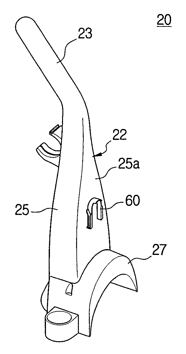
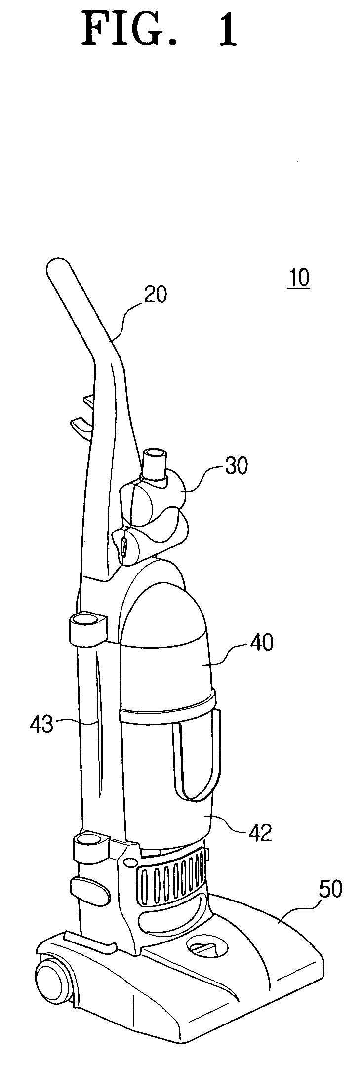
[0029]FIG. 1 is a perspective view illustrating an upright vacuum cleaner 10 employing a handle unit 20 according to an embodiment of the present disclosure.

[0030]Referring to FIG. 1, the upright vacuum cleaner 10 includes a cleaner body 40, a suction brush assembly 50, and a handle unit 20.

[0031]The cleaner body 40 includes a driving source (not shown) generating a suction force, a dust collector 42 collecting dust contain...


PUM


Abstract

The present disclosure relates to a handle unit for a vacuum cleaner. The handle unit for the vacuum cleaner for controlling a cleaner body of the vacuum cleaner includes a handle body of the vacuum cleaner; and a supporting unit projected from one side of the handle body, the supporting unit holding an accessory brush, wherein the supporting unit and the handle body is molded in a single piece by the injection molding process.

Description

CROSS-REFERENCE TO RELATED APPLICATIONS[0001]This application claims the benefit under 35 U.S.C. § 119(a) from Korean Patent Application No. 2006-0006408 filed Jan. 20, 2006 in the Korean Intellectual Property Office, the disclosure of which is incorporated herein by reference in its entirety.BACKGROUND OF THE INVENTION[0002]1. Field of the Invention[0003]The present disclosure relates to a handle unit for a vacuum cleaner. More particularly, the present disclosure relates to a handle unit for a vacuum cleaner having a supporting structure for accessories such as accessory brushes.[0004]2. Description of the Related Art[0005]Generally, an upright vacuum cleaner includes a suction brush assembly facing a surface to be cleaned, a cleaner body disposed at a top end of the suction brush assembly, and a handle unit disposed at a top end of the cleaner body for users to control the upright vacuum cleaner.[0006]A motor chamber and a dust collecting chamber are formed inside the cleaner bod...

Claims


Application Information

Patent Timeline
Patent Type & Authority Patents(United States)
IPC IPC(8): A47L9/32A47L9/26
CPCA47L9/0009A47L9/325A47L9/0027A47L9/00A47L9/32A47L5/28
Inventor KIM, TAE-GWANGCHO, JEONG-HEE
Owner SAMSUNG GWANGJU ELECTRONICS CO LTD
Why Eureka
Try Eureka