Method for measuring a medium flowing in a pipeline and measurement system therefor
What is Al technical title?
Al technical title is built by PatSnap Al team. It summarizes the technical point description of the patent document.
a technology of pipelines and mediums, applied in the direction of mass flow measurement devices, measurement devices, instruments, etc., can solve the problems of high installation costs, inability to precisely measure, and inability to use measurement signals in multiphase streams of mediums
Active Publication Date: 2008-08-05
ENDRESS HAUSER FLOWTEC AG
View PDF10 Cites 59 Cited by
Summary
Abstract
Description
Claims
Application Information
AI Technical Summary
This helps you quickly interpret patents by identifying the three key elements:
Problems solved by technology
Method used
Benefits of technology
Benefits of technology
[0059]An advantage of the invention is, additionally, to be seen also in the fact that the measurement system and, therefore, also the method corresponding therewith, can be implemented by connecting together even conventional inline measuring devices of the described kind with conventional pressure-difference measuring devices. In such case, it is of special advantage, when at least one of the measuring devices applied for the measurement system of the invention has a programmable measuring device electronics, since, thereby, the measurement system can be implemented by solely slight reconfiguring of the firmware, especially the measurement signal evaluation, or the software components concerning the measured value determination, as the case may be, and a corresponding electric connection of the two measuring device electronics together, be it via a superordinated field bus or directly via the measured value issuing and / or in-reading, signal ports of the respective measurement device electronics. A further advantage of the invention is, additionally, to be seen in the fact that, for the measurement system, inline measuring devices established in industrial measurements and automation technology, exhibiting the most varied of measurement principles, such as e.g. those comprising a flow measurement pickup of vibration type, as well as also those using magneto-inductive measurement pickups or ultrasonic measurement pickups, can be used.
[0060]The invention and further advantages will now be explained in the following on the basis of examples of embodied in the figures of the drawing; equal parts are provided with equal reference characters in the figures. In case helpful for overviewability, repetition of reference characters in subsequent figures is omitted. The figures show as follows:
Problems solved by technology
As a result, these measurement signals in the case of multiphase streams of medium are practically unusable for a highly accurate measurement of the physical flow parameter of interest.
However, a significant disadvantage of such, actually quite precisely measuring, measurement systems can reside in their increased complexity and the accompanying high installation costs, on the one hand, and the high servicing and maintenance costs, on the other hand.
Moreover, such measurement systems possess, most often, a relatively high requirement for space.
Method used
Image
Click on the blue label to locate the original text in one second.
Reading with bidirectional positioning of images and text.
Examples
Embodiment Construction
[0064]While the invention is susceptible to various modifications and alternative forms, exemplary embodiments thereof have been shown by way of example in the drawings and will herein be described in detail. It should be understood, however, that there is no intent to limit the invention to the particular forms diclosed, but on the contraiy, the intention is to cover all modifications, equivalents, and alternatives falling within the spirit and scope of the invention as defined by the intended claims.
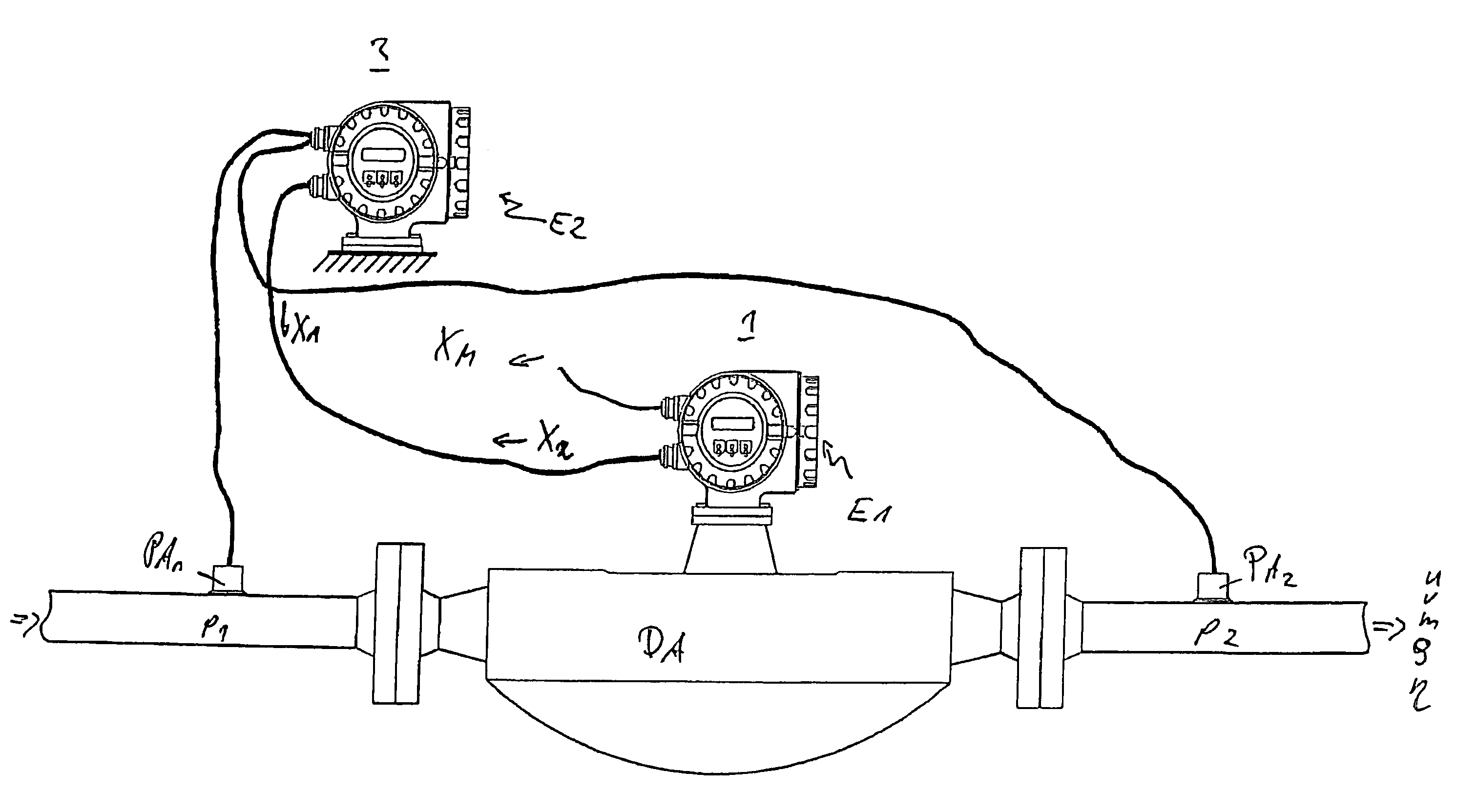
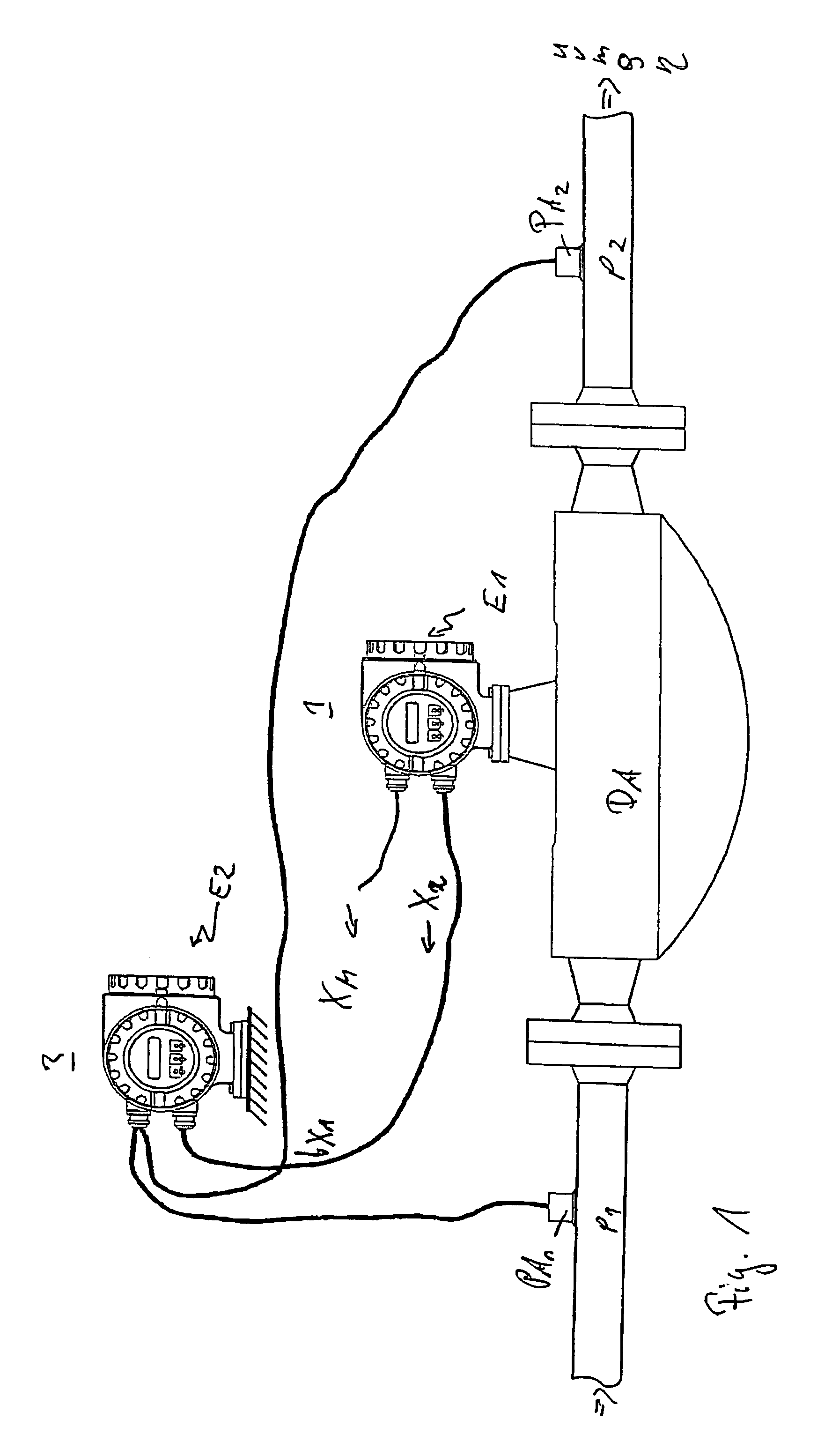
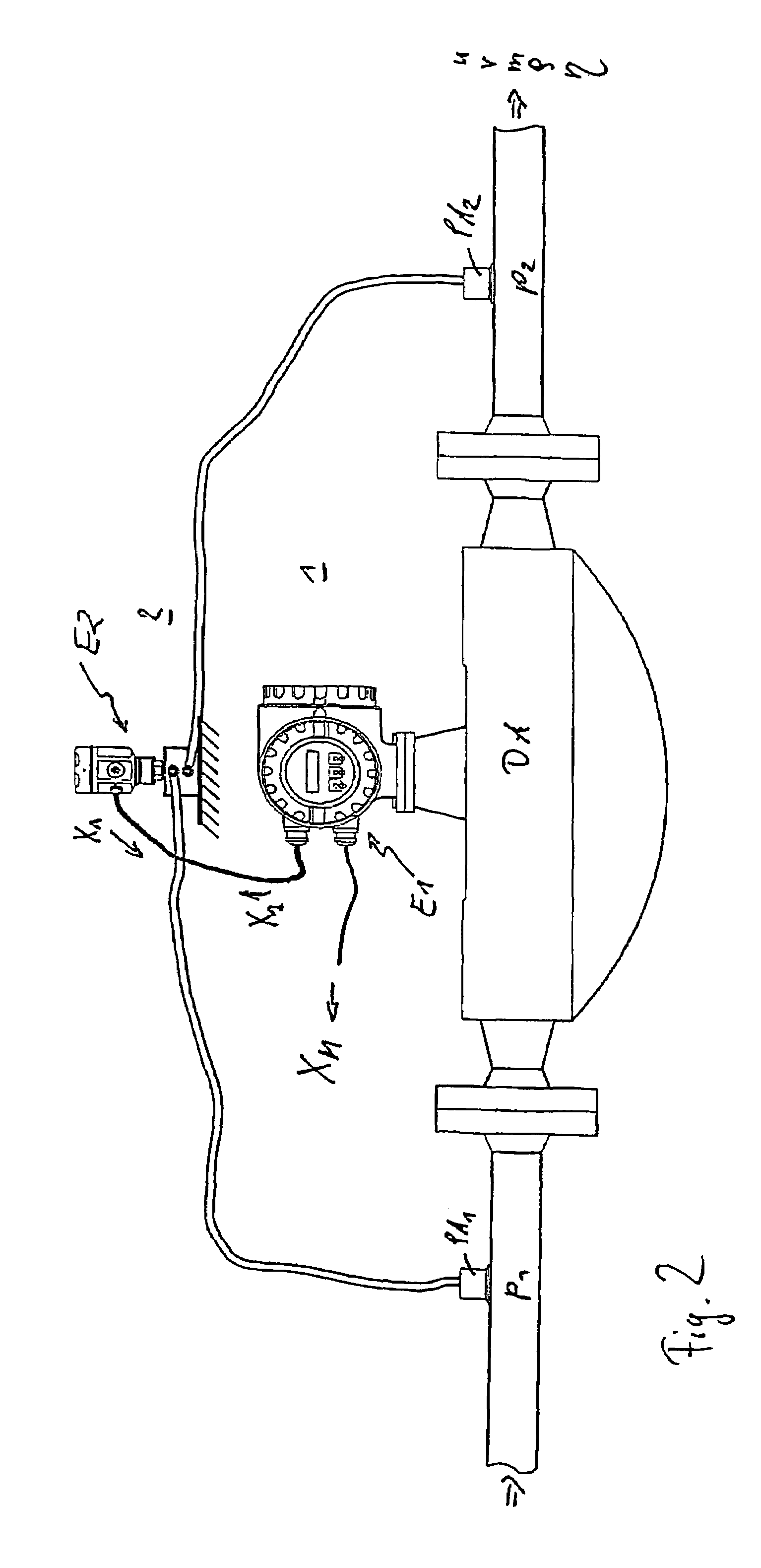
[0065]FIGS. 1 to 3 show, in each case, an example of an embodiment for a measurement system, especially one built modularly and / or with the principle of diversity, which is suited for, and provided for, very robustly measuring at least one physical, flow parameter, especially a mass flow rate m and / or volume flow rate v and / or a flow velocity u, of a medium flowing in a pipeline (not shown) and for representing such in at least one, corresponding, measured value XM. Especially, the mea...
PUM
Abstract
For measuring a medium, the medium flows through at least one inline measuring device measuring tube joined into the course of a pipeline, especially a measuring tube which vibrates, at least at times. Using an inline measuring device sensor arrangement arranged on the measuring tube and / or in its vicinity and reacting, at least mediately, to changes of the at least one physical parameter of the medium, at least one measurement signal is produced, which is influenced by at least one physical parameter of the medium in the measuring tube. Additionally, pressures effective in the medium are registered, in order to determine repeatedly a pressure difference existing in the flowing medium at least in part along the at least one measuring tube. Taking into consideration a pressure difference currently determined for the flowing medium, as well as applying a transfer function, measured values of a first kind are produced, which represent, following in time one after the other, the at least one flow parameter to be measured for the medium. The transfer function determines, in such case, at least how the measured values of the first kind are generated under application of the pressure difference currently determined for the flowing medium. Taking into consideration the at least one measurement signal produced by means of the sensor arrangement of the inline measuring device, the transfer function is repeatedly adapted to the medium to be measured. The method serves especially for the measuring of media, which are, at least at times, present as two, or more, phases, of which at least one is a fluid phase.
Description
[0001]This application claims the benefit of provisional application No. 60 / 720,456 filed on Sep. 27, 2005.FIELD OF THE INVENTION[0002]The invention relates to a method for measuring at least one physical, flow parameter, especially a mass flow and / or a density and / or a viscosity, of a two, or more, phase medium flowing in a pipeline, as well as a measurement system suited therefor.BACKGROUND OF THE INVENTION[0003]In process measurements and automation technology, for the highly accurate measurement of physical parameters, such as e.g. mass flow, density and / or viscosity, of a medium flowing in a pipeline, for example a gas and / or a liquid, often such inline measuring devices are used, which, by means of a measurement pickup, or transducer, of vibration-type, through which the medium is flowing, and a measurement and operating circuit connected thereto, effect reaction forces in the medium, forces such as e.g. Coriolis forces corresponding with mass flow, inertial forces correspondi...
Claims
Application Information
Patent Timeline
Application Date:The date an application was filed.
Publication Date:The date a patent or application was officially published.
First Publication Date:The earliest publication date of a patent with the same application number.
Issue Date:Publication date of the patent grant document.
PCT Entry Date:The Entry date of PCT National Phase.
Estimated Expiry Date:The statutory expiry date of a patent right according to the Patent Law, and it is the longest term of protection that the patent right can achieve without the termination of the patent right due to other reasons(Term extension factor has been taken into account ).
Invalid Date:Actual expiry date is based on effective date or publication date of legal transaction data of invalid patent.
