Surgical stapling device

a stapling device and surgical technology, applied in the direction of surgical staples, surgical forceps, paper/cardboard containers, etc., can solve the problems and lacking in several aspects of the known prior art surgical staplers, etc., to achieve the effect of reducing the overall strength, increasing the strength, and reducing the size of the head portion profil

Inactive Publication Date: 2008-08-05
COVIDIEN LP
View PDF151 Cites 1433 Cited by
  • Summary
  • Abstract
  • Description
  • Claims
  • Application Information

AI Technical Summary

Benefits of technology

[0013]A pawl mechanism is supported in the body and includes a clamping pawl and a firing pawl. The clamping pawl functions to prevent return of the approximation mechanism after the trigger has moved through approximately three quarters of the approximation stroke. The clamping pawl also provides an audible and tactile indication that the device has been moved to the approximately three quarter approximated position. The firing pawl functions to provide an audible indication that the device is in a fire-ready position. The firing pawl also functions to lock the trigger in a compressed position after firing of the device has occurred to provide a visual indication that firing has occurred. A release button is provided to return the approximation mechanism to the retracted position at any point of operation of the device. The pivotable trigger, the release button and the thumb button are all disposed adjacent the handle portion of the device and are operable by the surgeon using a single hand.
[0014]The anvil assembly of the surgical stapling device is provided with a stiffener plate to provide increased strength to the assembly. By using the stiffener plate, the head portion profile can be reduced in size without reducing the overall strength of the anvil assembly.

Problems solved by technology

Known prior art surgical staplers are lacking in several respects.
Firstly, the use of multiple actuators to effect approximation and firing of the instruments complicate the manufacture and operation of the instrument and, in most cases, require the surgeon to use two hands to hold and operate the instrument.
Secondly, the instruments in which the alignment pin assembly is operatively associated with the approximation mechanism require that the instrument be approximated to advance the alignment pin assembly, despite the fact that a surgeon may prefer to advance the alignment pin assembly prior to approximation.

Method used


Image

  • Surgical stapling device
  • Surgical stapling device
  • Surgical stapling device

Examples


Embodiment Construction

[0075]Embodiments of the presently disclosed surgical stapling device will now be described in detail with reference to the drawings, wherein like reference numerals designate identical or corresponding elements in each of the several views.

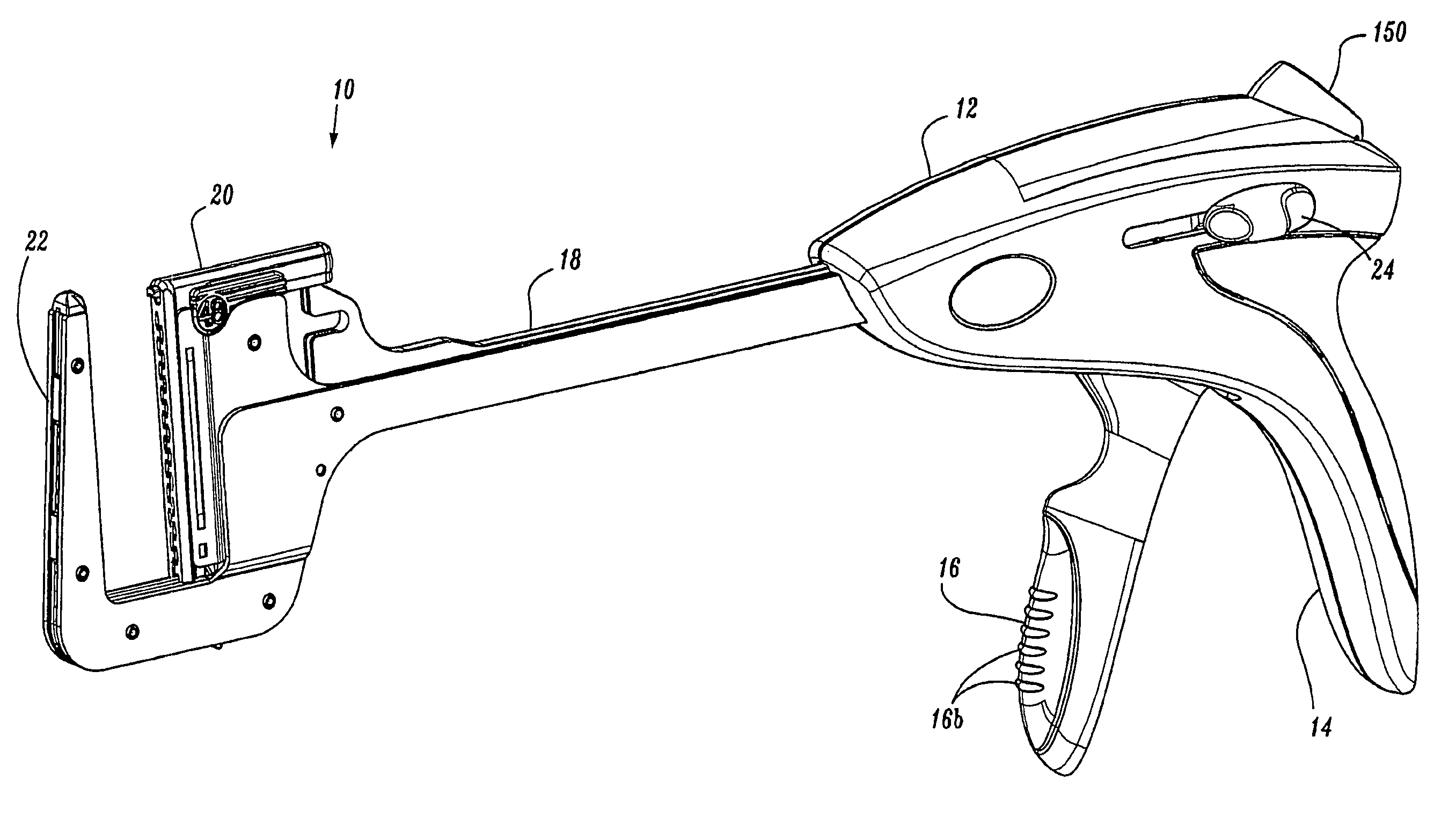
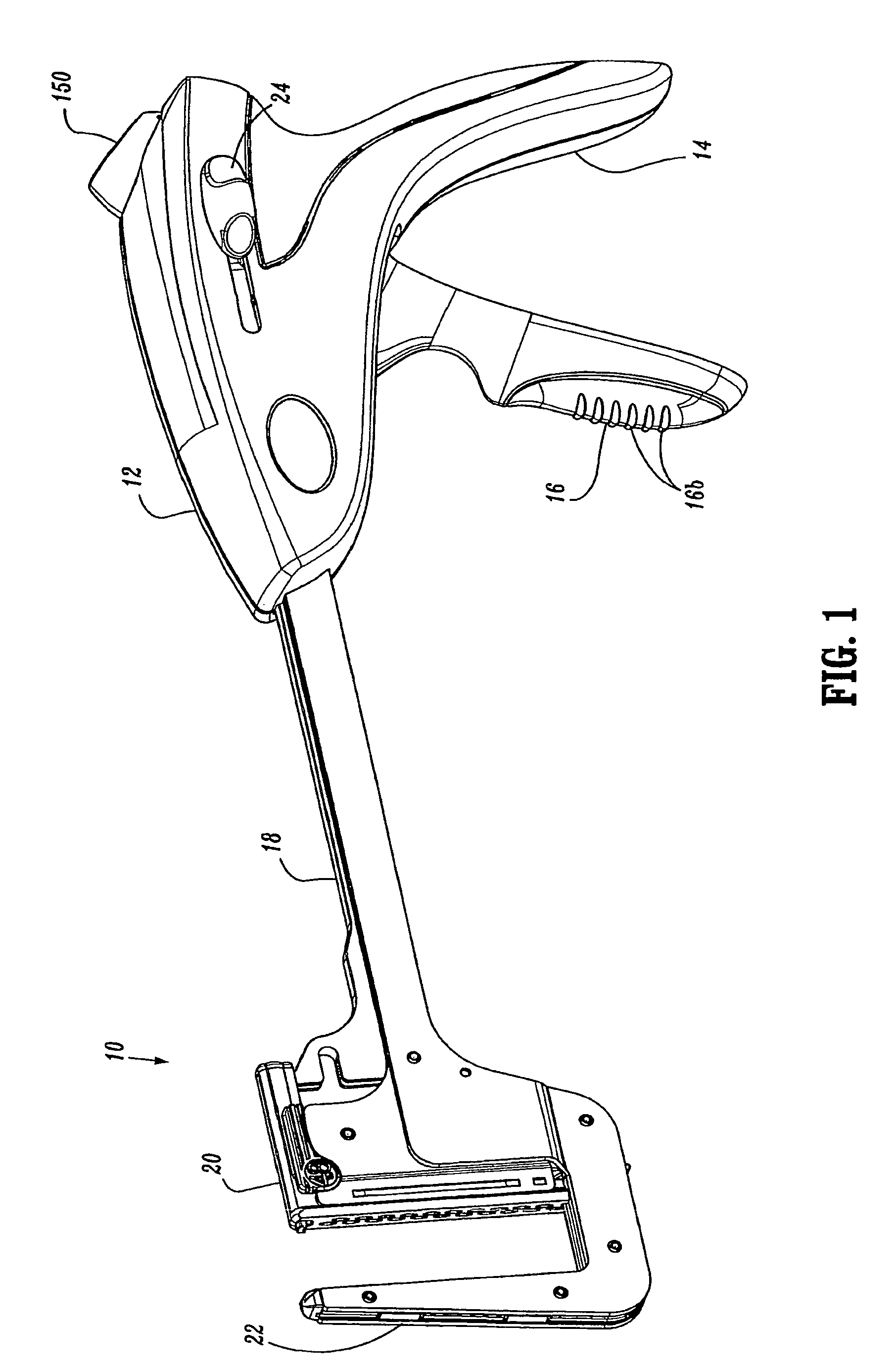
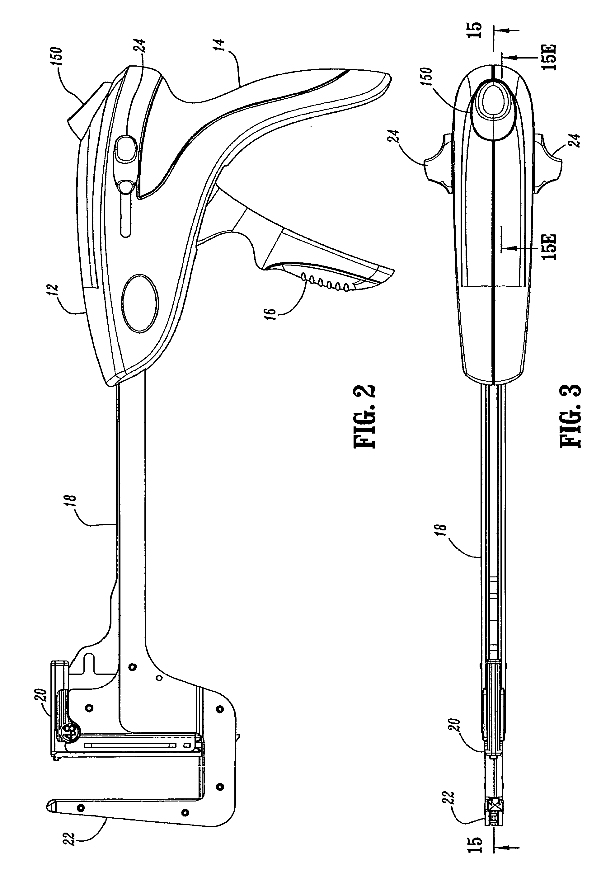
[0076]The presently disclosed surgical stapling device shown generally as 10 in FIGS. 1-3 includes a body 12 defining a stationary handle 14, a pivotable trigger 16, an elongated central body portion 18, a cartridge assembly 20 and an anvil assembly 22. A thumb button 24 is slidably positioned on each side of body 12. Thumb buttons 24 are movable to manually advance an alignment pin assembly in a manner to be described in detail below. A release button 150 of a release mechanism 26 (FIG. 13) is positioned on the proximal end of body 12 and is depressible to allow cartridge assembly 20 to return from an approximated position disposed adjacent to anvil assembly 22 to a position spaced from anvil assembly 22 (as shown). Operation of release mechanis...


PUM

PropertyMeasurementUnit
massaaaaaaaaaa
strengthaaaaaaaaaa
sizeaaaaaaaaaa

Abstract

A surgical stapling device for applying an array of surgical staples to tissue is provided. The stapling device includes an approximation mechanism for moving a cartridge assembly and an anvil assembly between spaced and approximated positions and a firing mechanism for ejecting the array of staples from the cartridge assembly. A single trigger is operable to effect approximation and firing of the device. The device also includes an alignment pin assembly which can be selectively manually or automatically advanced. The anvil assembly includes a stiffener plate which allows the device to have a reduced head portion profile.

Description

CROSS-REFERENCE TO RELATED APPLICATIONS[0001]This application is a continuation-in-part of U.S. patent application Ser. No. 11 / 436,282 filed May 18, 2006, which is a continuation of U.S. patent application Ser. No. 11 / 125,790, filed on May 10, 2005 now abandoned, which is a continuation of U.S. patent application Ser. No. 10 / 783,126 filed on Feb. 20, 2004, now abandoned, which is a continuation of U.S. patent application Ser. No. 09 / 687,815, filed on Oct. 13, 2000, now U.S. Pat. No. 6,817,508. The entire contents of each of these prior applications is incorporated herein by reference.BACKGROUND[0002]1. Technical Field[0003]The present disclosure relates generally to a surgical stapling apparatus and, more specifically, to a surgical stapling apparatus having a single trigger for approximating anvil and cartridge assemblies and for ejecting an array of staples from the cartridge assembly.[0004]2. Background of Related Art[0005]Surgical stapling instruments used for applying parallel ...

Claims


Application Information

Patent Timeline
Patent Type & Authority Patents(United States)
IPC IPC(8): A61B17/00
CPCA61B17/072A61B2017/00367A61B2017/0038A61B2017/07214A61B2019/4857A61B2017/2925A61B2017/2945A61B2017/320052A61B2017/07264A61B2090/0811
Inventor RACENET, DAVID C.WELLS, TIMOTHY N.MARCZYK, STANISLAW
Owner COVIDIEN LP
Why Eureka
Try Eureka