
Image forming apparatus

a technology of image forming apparatus and forming tube, which is applied in the direction of electrographic process apparatus, printing, instruments, etc., can solve the problems of productivity degradation, and achieve the effect of reducing the time required for image testing

Inactive Publication Date: 2008-08-05
RICOH KK
View PDF8 Cites 6 Cited by
  • Summary
  • Abstract
  • Description
  • Claims
  • Application Information

AI Technical Summary

Benefits of technology

The present invention provides an image forming apparatus that can reduce the time required for image testing. This is achieved by an operations part that can operate the apparatus in a predetermined special mode different from a normal mode in case of specific machine numbers or input through specific keys. Additionally, the apparatus can also be operated in a predetermined special mode when connected to an external connection part through a connector. This helps to avoid unnecessary operations for image checking and reduces the time required for image testing.

Problems solved by technology

Because of this, since unnecessary operations are conducted for such a check, it takes a lot of time for image checking so that productivity may be degraded.

Method used


Image

  • Image forming apparatus
  • Image forming apparatus
  • Image forming apparatus

Examples


Embodiment Construction

[0028]A description of examples and exemplary embodiments of the present disclosure is now given, with reference to FIG. 1 through FIG. 8.

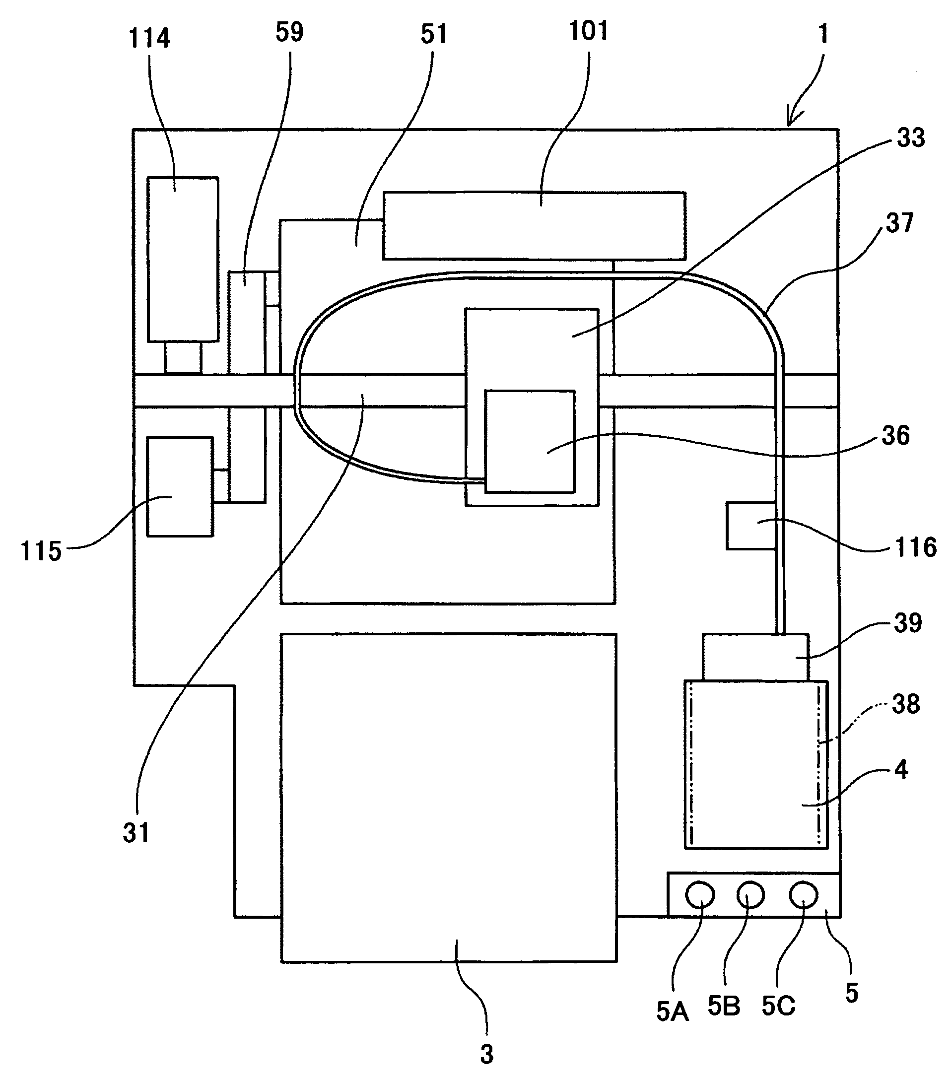
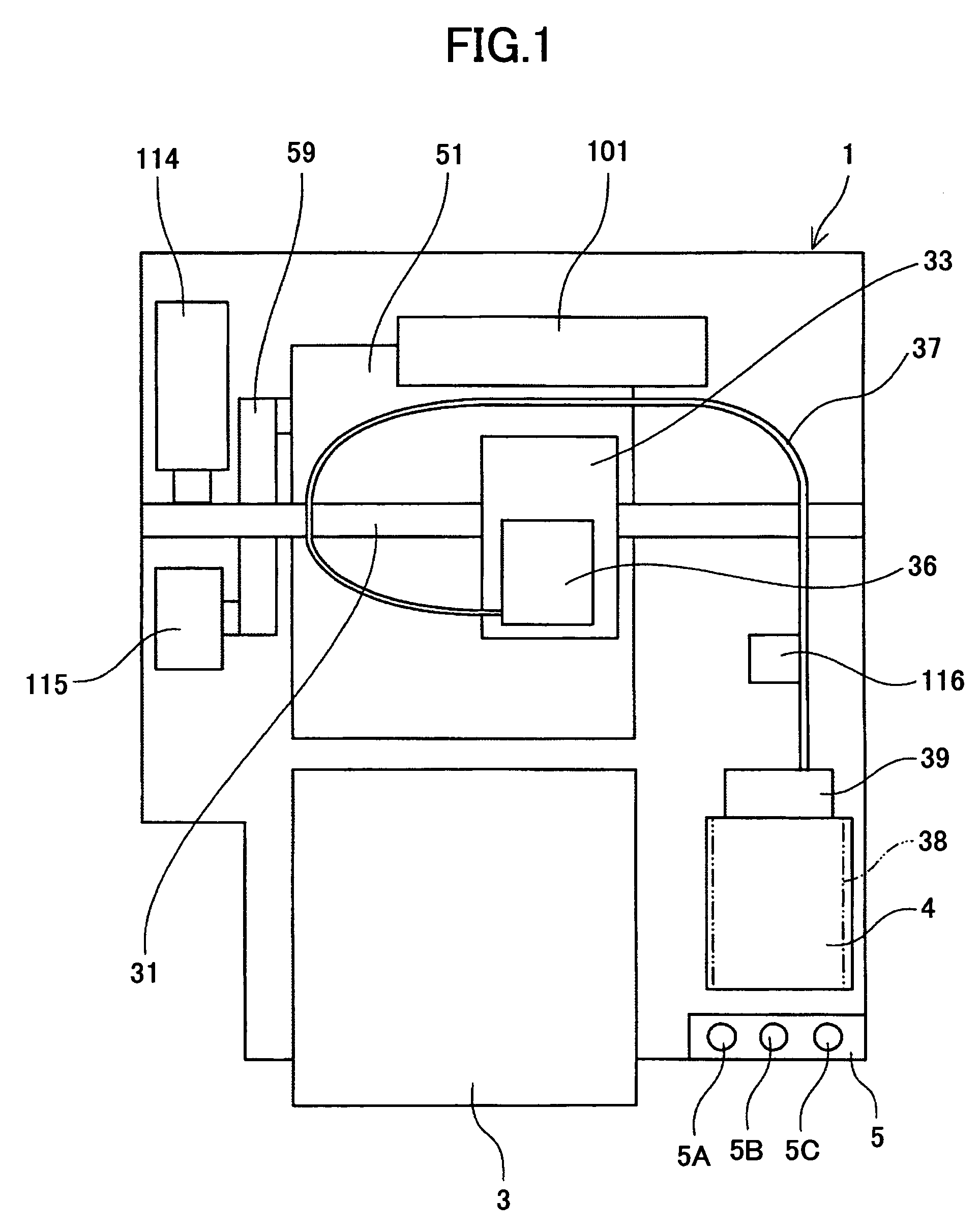
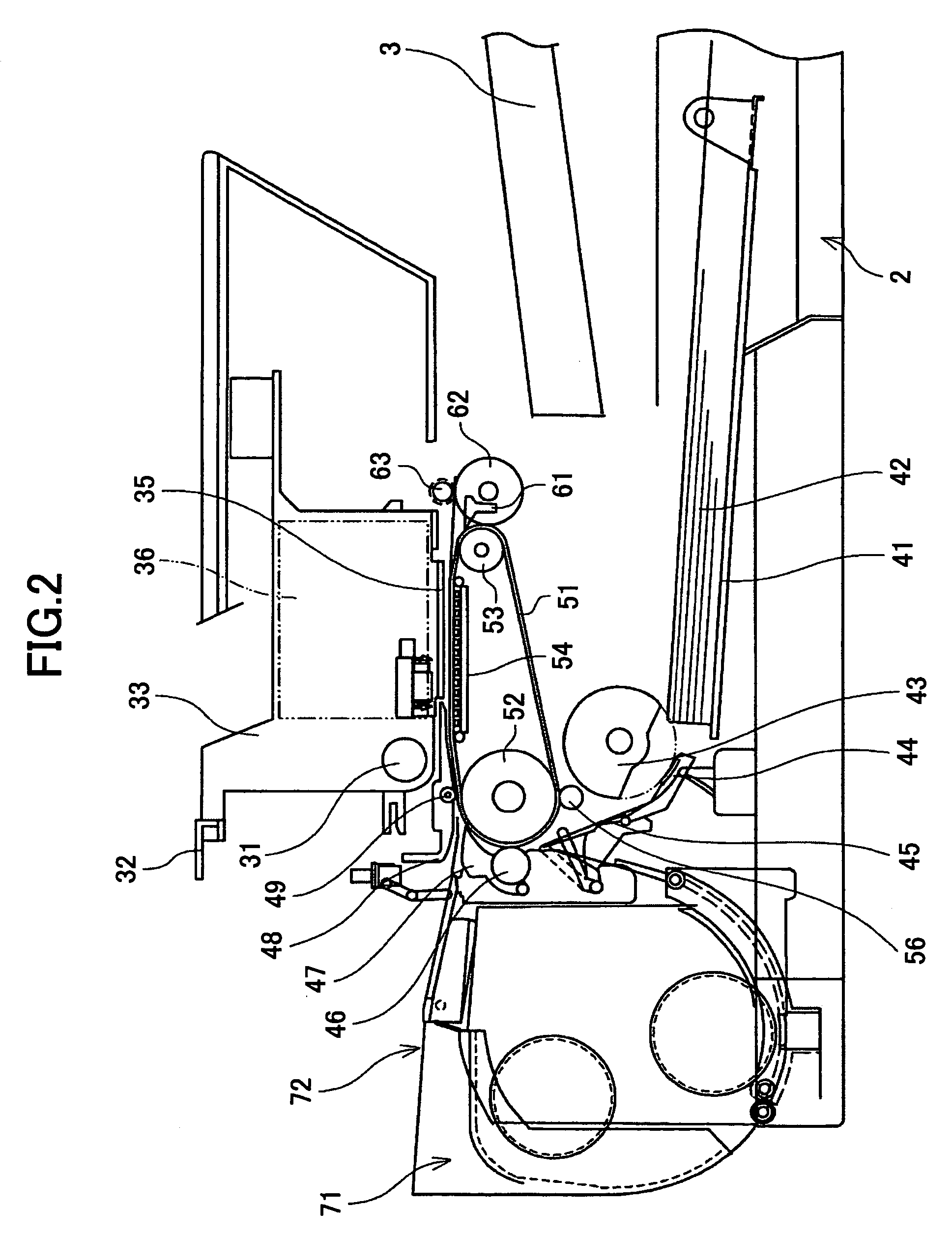
[0029]FIG. 1 is a structural diagram of an inkjet recording apparatus, which is an example of an image forming apparatus according a first embodiment of the present invention. FIG. 2 is a side view of the inkjet recording apparatus shown in FIG. 1. FIG. 3 is a plan view of a main part of the inkjet recording apparatus shown in FIG. 1.

[0030]At a front surface side of the image forming apparatus 1, a paper supply cassette 2 where papers are provided, a paper eject tray 3 in which the paper where the image is recorded (formed) is provided, a cartridge installation part 4 where an ink cartridge that is a recording liquid cartridge is detachably provided, and an operations panel 5 including a switch for giving a designated instruction to the image forming apparatus and a display part displaying a remaining amount of fluid in the ink cartridge are provi...


PUM


Abstract

An image forming apparatus whereby recording liquid is jetted onto a recording medium so that an image is formed, the image forming apparatus includes an operations part configured to operate the apparatus in a predetermined special mode different from a normal mode in a case where a machine number stored in advance is a specific character string.

Description

BACKGROUND[0001]1. Technical Field[0002]The present disclosure relates to image forming apparatuses.[0003]2. Description of the Related Art[0004]A serial scan type or line type image forming apparatus is known as an image forming apparatus such as a printer, facsimile, copier, plotter, printer or multi-purpose functional machine of the printer and the facsimile. The serial scan type or line type image forming apparatus includes an image forming part for jetting a liquid drop of recording liquid onto a recording medium such as a paper so that image forming, such as printing or recording, can be implemented.[0005]For the purpose of improvement of the productivity of such an image forming apparatus, for example, Japan Laid-Open Patent Application Publication No. 2001-347655 discloses that an ink jet head, an IC for driving the ink jet head, and plural electronic parts for driving the ink jet head as the constituent members of this ink jet head module are set on a TAB tape.[0006]In addi...

Claims


Application Information

Patent Timeline
Patent Type & Authority Patents(United States)
IPC IPC(8): B41J2/145G03G15/00
CPCB41J2/17546B41J2/17509
Inventor SADANO, KOHICHI
Owner RICOH KK
Learn More