Cutting tool assembly and cutting head therefor

a technology of cutting tool and cutting head, which is applied in the direction of shaping cutters, manufacturing tools, twist drills, etc., can solve the problems of deformation of the cutting edge, affecting the delivery of hot glue to the cutting edge,

Active Publication Date: 2008-08-05
ISCAR LTD
View PDF40 Cites 63 Cited by
  • Summary
  • Abstract
  • Description
  • Claims
  • Application Information

AI Technical Summary

Problems solved by technology

However, when assembled, the cutting head coupling portions fully overlie the shank coupling portions, which may hinder coolant delivery to the cutting edges, and may require formation of coolant passages through the cutting head.
However, because of their reduced thickness, some additional means of clamping, such as screws, may be required, and even then, tangential forces acting on the cutting edges may disadvantageously deform the shank.

Method used


Image

  • Cutting tool assembly and cutting head therefor
  • Cutting tool assembly and cutting head therefor
  • Cutting tool assembly and cutting head therefor

Examples


Embodiment Construction

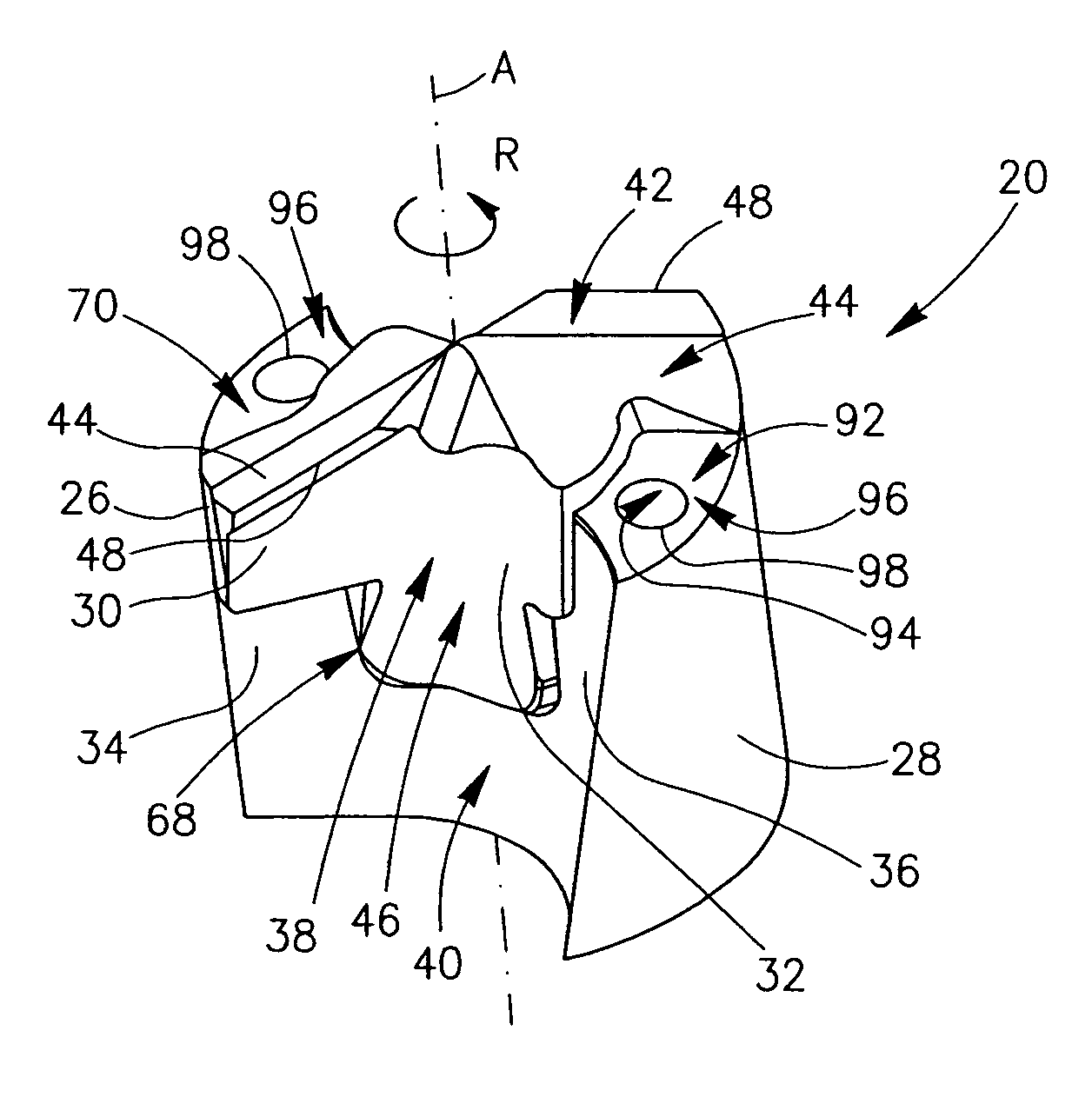
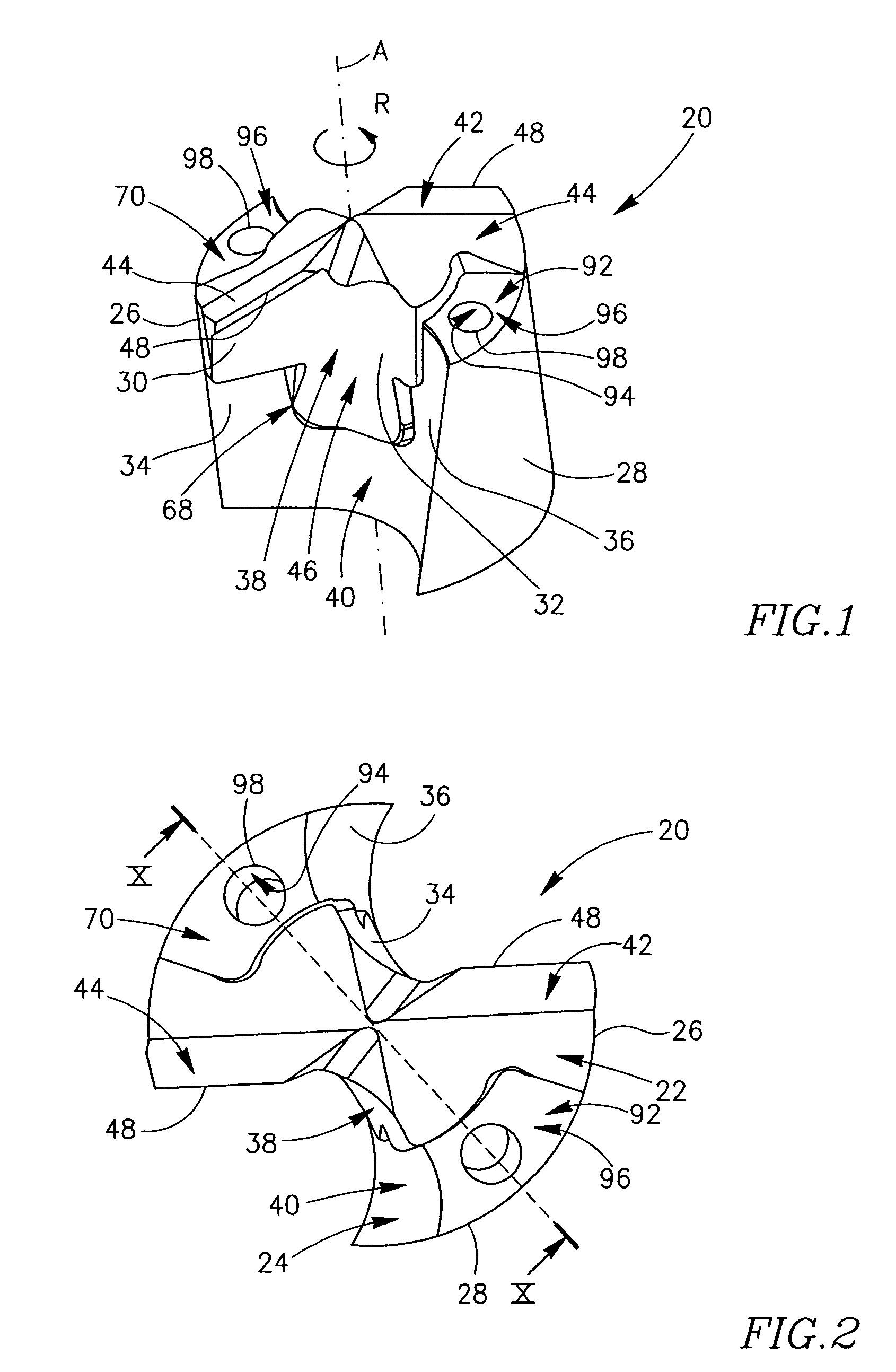
[0034]The present invention relates to a rotary cutting tool assembly, and will be exemplified by means of a drill. Attention is first drawn to FIGS. 1 and 2. A drill 20 in accordance with a first embodiment of the present invention comprises a replaceable cutting head 22 and a shank 24 having a common axis of rotation A defining a front-to rear direction and a direction of rotation R. The cutting head 22 and the shank 24 have mating and continuous cutting head and shank outer cylindrical surfaces 26, 28, and mating cutting head and shank leading and trailing flute sections 30, 32, 34, 36 which, when the drill 20 is assembled, form two continuous, preferably helical, cutting head and shank flutes 38, 40. The drill 20 thus has a 180° rotational symmetry around the axis of rotation A.

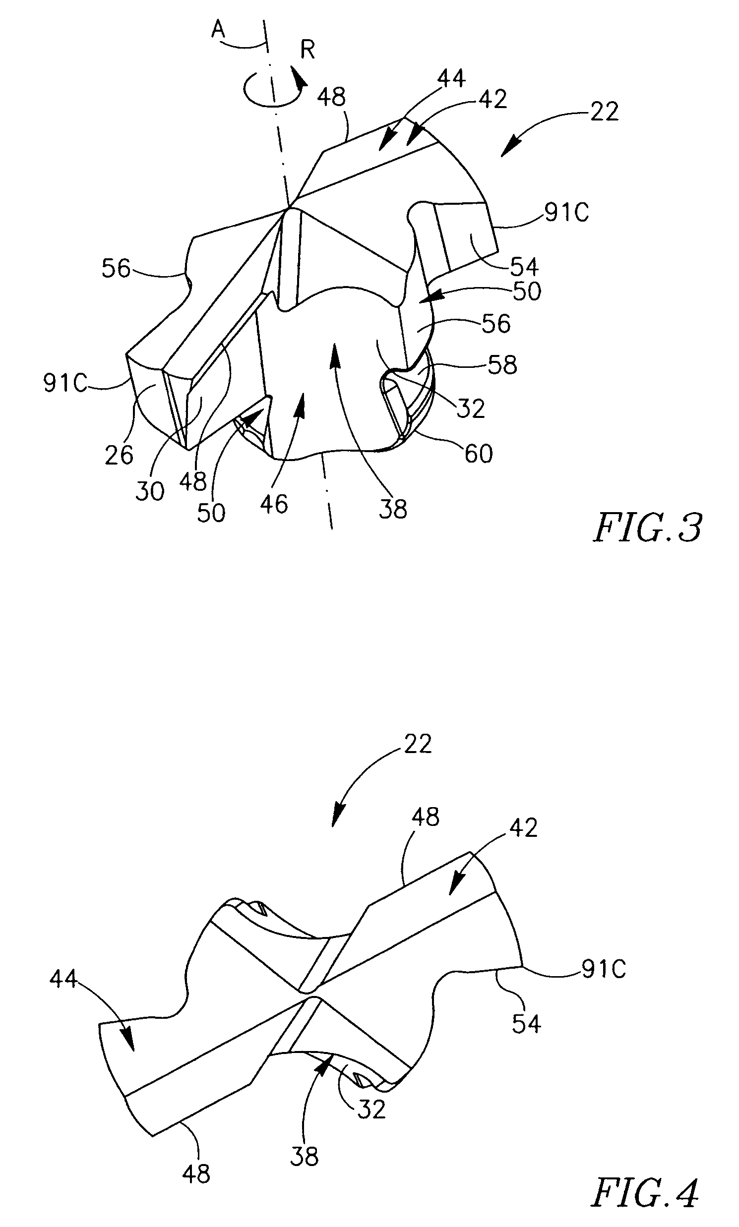
[0035]Attention is now drawn to FIGS. 3 to 5. The cutting head 22 is typically made of a solid, hard metal, such as cemented metal carbide (e.g. tungsten carbide) and is generally manufactured by form-pre...


PUM

PropertyMeasurementUnit
tilt angleaaaaaaaaaa
radial deviation angleaaaaaaaaaa
tilt angleaaaaaaaaaa

Abstract

A rotary cutting tool comprising a solid cutting head mounted to a shank. The cutting head comprises a cutting portion adjacent a cutting head front face and a mounting portion integrally formed therewith and extending rearwardly therefrom. The shank comprises a receiving portion extending rearwardly from a shank front face. When the cutting head is secured to the shank, the mounting portion is received in the receiving portion, and the shank front face is forwardly exposed and adjacent the cutting head front face.

Description

FIELD OF THE INVENTION[0001]The present invention relates to a cutting tool assembly comprising a replaceable cutting head and a shank on which the cutting head is mounted, for use in rotary cutting operations such as drilling, milling and the like.BACKGROUND OF THE INVENTION[0002]U.S. Pat. No. 5,957,631 discloses a rotary cutting tool comprising a cutting head releasably coupled to a shank, the cutting head and the shank being bounded by cutting head and shank peripheral surfaces mating in shape and dimensions, and having cutting edges at a front end of the cutting head. The cutting head and the shank are advantageously coupled by a dovetail coupling arrangement, providing secure retention and stable coupling, without relying on other coupling means, such as screws. This greatly simplifies assembly and disassembly of cutting heads to / from the shank. However, when assembled, the cutting head coupling portions fully overlie the shank coupling portions, which may hinder coolant delive...

Claims


Application Information

Patent Timeline
Patent Type & Authority Patents(United States)
IPC IPC(8): B23B51/02B23B51/06B23C
CPCB23B51/02B23B2251/02Y10T408/9098Y10T408/44Y10T407/1908Y10S408/713B23B51/00
Inventor HECHTMEN, DANIEL
Owner ISCAR LTD
Why Eureka
Try Eureka