Pedal device for drum

a pedal and drum technology, applied in the field of pedal devices, can solve the problems of increasing material costs, affecting the playing of bass drums, and difficulty in playing bass drums, and achieve the effect of increasing the return speed of the pedal and being easy to play

Active Publication Date: 2008-08-05
HOSHINO GAKKI COMPANY LIMITED
View PDF9 Cites 11 Cited by
  • Summary
  • Abstract
  • Description
  • Claims
  • Application Information

AI Technical Summary

Benefits of technology

[0006]It is an object of the present invention to provide a pedal device that increases the return speed of the pedal and makes a drum easier to play.

Problems solved by technology

This may hinder with the playing of the bass drum.
This would make it difficult to play the bass drum.
However, this would increase the material cost and be an obstacle to lowering the cost of the pedal device 100.
Moreover, if the weight of the beater 105 is reduced, the desired loudness may not be obtained when beating the bass drum.

Method used


Image

  • Pedal device for drum
  • Pedal device for drum
  • Pedal device for drum

Examples


Embodiment Construction

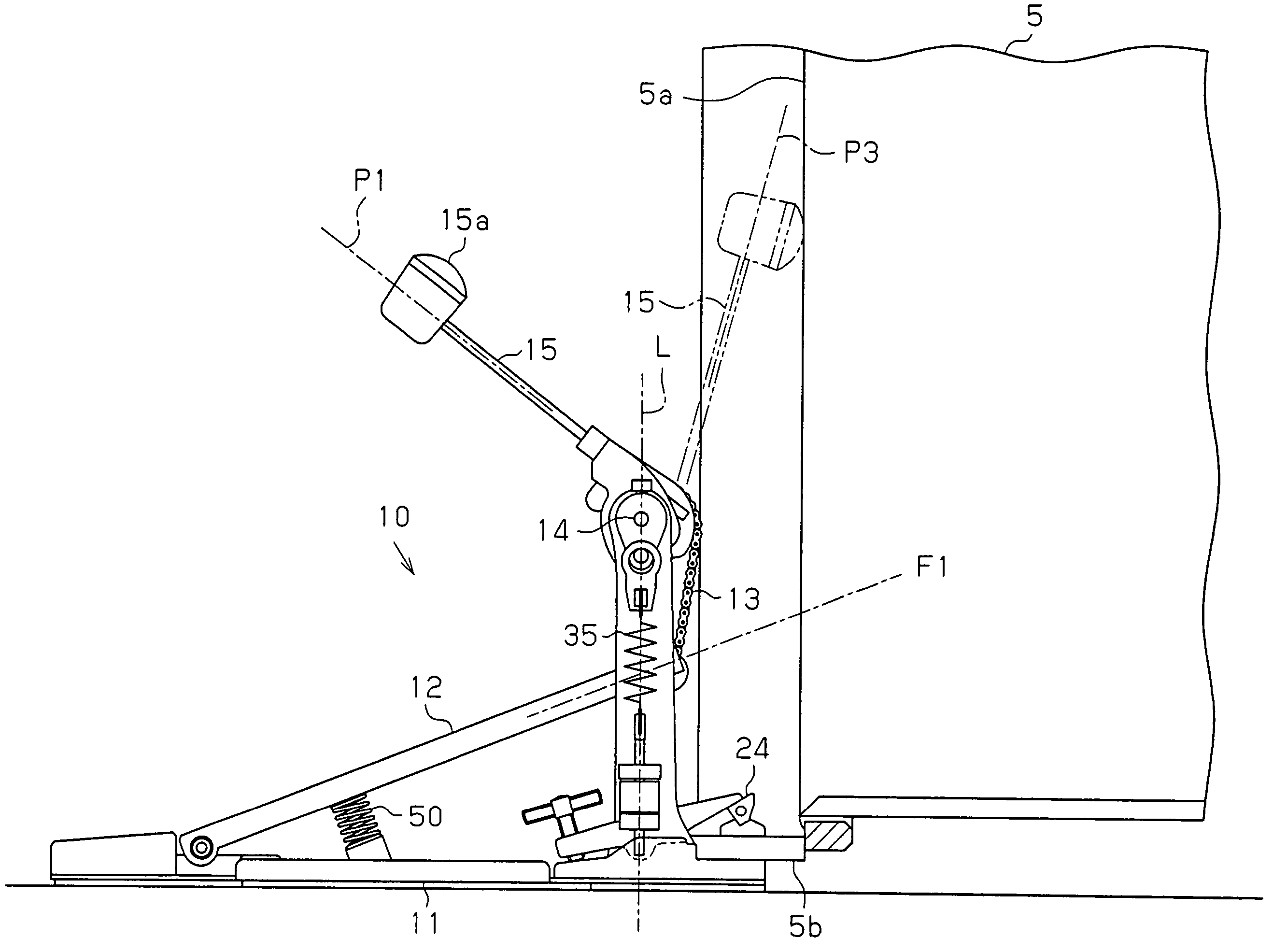
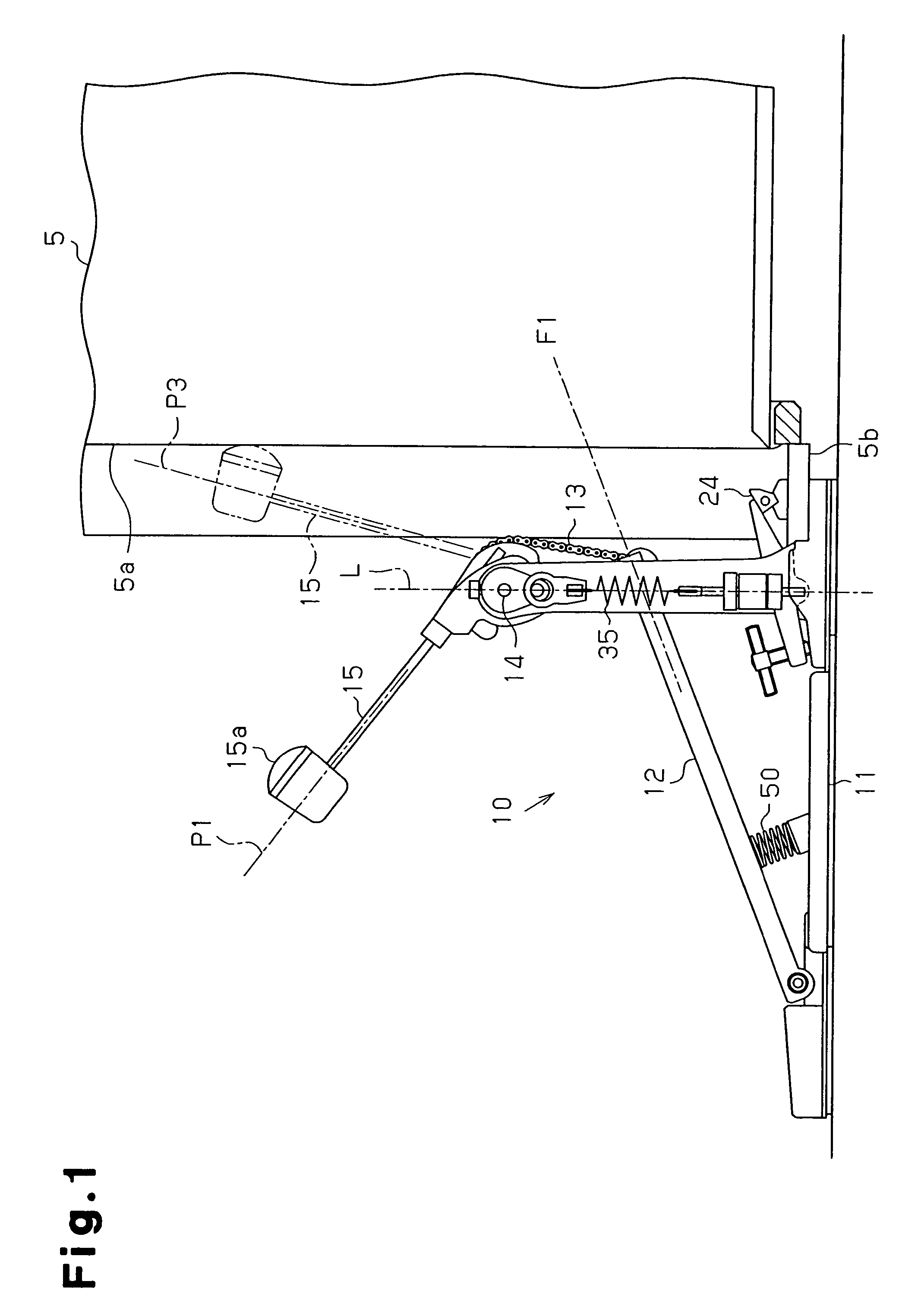
[0023]A preferred embodiment of the present invention will now be described with reference to FIGS. 1 to 5.

[0024]Referring to FIG. 1, a pedal device 10 includes a base plate 11, a pedal 12, a chain 13, a pivot shaft 14, a beater 15, and an extension coil spring 35. The pedal device 10 is used in a state in which the base plate 11, which functions as a base, is connected to a bass drum 5, with a beating surface 15a of the beater 15 facing toward the bass drum 5. When playing the bass drum 5 with the pedal device 10, a drummer depresses or raises the pedal 12 with his or her foot to pivot the beater 15 in a reciprocating manner together with the pivot shaft 14. In the description of the pedal device 10, the side connected to the bass drum 5 (right side as viewed in FIG. 1) is referred to as a front portion, and the side opposite from the bass drum 5 (left side as viewed in FIG. 1) is referred to as a rear portion.

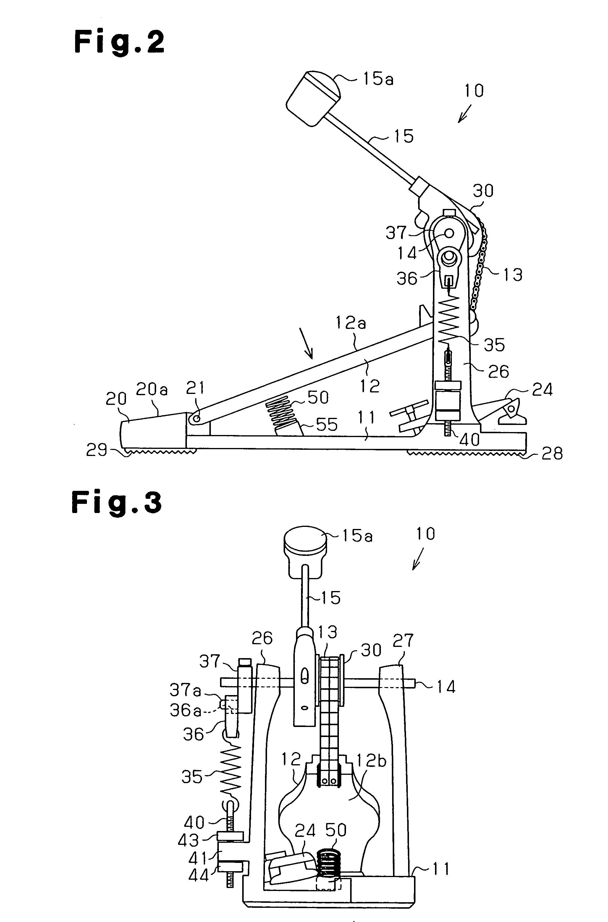
[0025]Referring to FIGS. 2 and 3, the pedal device 10 includes a base pl...


PUM


Abstract

A pedal device for a drum includes a base plate, a pedal, a chain, a pivot shaft, a beater, and an extension coil spring. When the pedal is freed from a depressed state, the urging force of the extension coil spring returns the beater from an operation position to a suspended position and returns the pedal to a standby position. A compression coil spring is arranged between the pedal and the base plate.

Description

BACKGROUND OF THE INVENTION[0001]The present invention relates to a pedal device used when playing a drum such as a bass drum.[0002]With reference to FIG. 11, a pedal device 100 includes a base plate 101, a pedal 102, a chain 103, a pivot shaft 104, a beater 105, and an extension coil spring 110. Two arms 107 project upward from the front portion of the base plate 101. The two arms 107 pivotally support the pivot shaft 104. The beater 105 and a wheel 108 are attached to the pivot shaft 104. The pedal 102 is pivotally attached to a rear portion of the base plate 101 by a support shaft 106. The chain 103 connects the pivot shaft 104 and the pedal 102. The chain 103 is wound on the wheel 108. In this state, one end of the chain 103 is fixed to the wheel 108, and the other end of the chain 103 is fixed to a movable end of the pedal 102. The extension coil spring 110 is connected between a cam 111, which is connected to the pivot shaft 104, and an adjustment screw 112, which is located a...

Claims


Application Information

Patent Timeline
Patent Type & Authority Patents(United States)
IPC IPC(8): G10D13/02
CPCG10D13/006G10D13/11
Inventor SATO, NAOKI
Owner HOSHINO GAKKI COMPANY LIMITED
Why Eureka
Try Eureka