Coupled FBAR filter

a filter and fbar technology, applied in the field of coupling fbar filters, can solve the problems of deteriorating filter characteristics and reducing filter characteristics to less, and achieve the effect of superb filter characteristics

Inactive Publication Date: 2008-08-05
PANASONIC CORP
View PDF7 Cites 8 Cited by
  • Summary
  • Abstract
  • Description
  • Claims
  • Application Information

AI Technical Summary

Benefits of technology

[0014]Therefore, an object of the present invention is to provide a coupled FBAR filter efficiently using the generated charge in input / output vibration portions and having superb filter characteristics. Another object of the present invention is provide a ladder-type filter, a duplexer and a communication device using such a coupled FBAR filter.
[0025]As described above, according to the present invention, the generated charge can be efficiently used, and smaller-loss and wider-band characteristics can be realized. Using such a coupled FBAR filter, the performance of the ladder-type filter, the duplexer and the communication device is improved.

Problems solved by technology

However, as shown in FIG. 28 and FIG. 29, the distance between the two or three input / output vibration portions (two or three electrode pairs) cannot reduced to less than a certain distance because the distance is restricted by the conditions for producing the electrodes.
As a result, a part of the generated charge is consumed by a non-electrode portion as a loss, which deteriorates the filter characteristics.

Method used


Image

  • Coupled FBAR filter
  • Coupled FBAR filter
  • Coupled FBAR filter

Examples


first embodiment

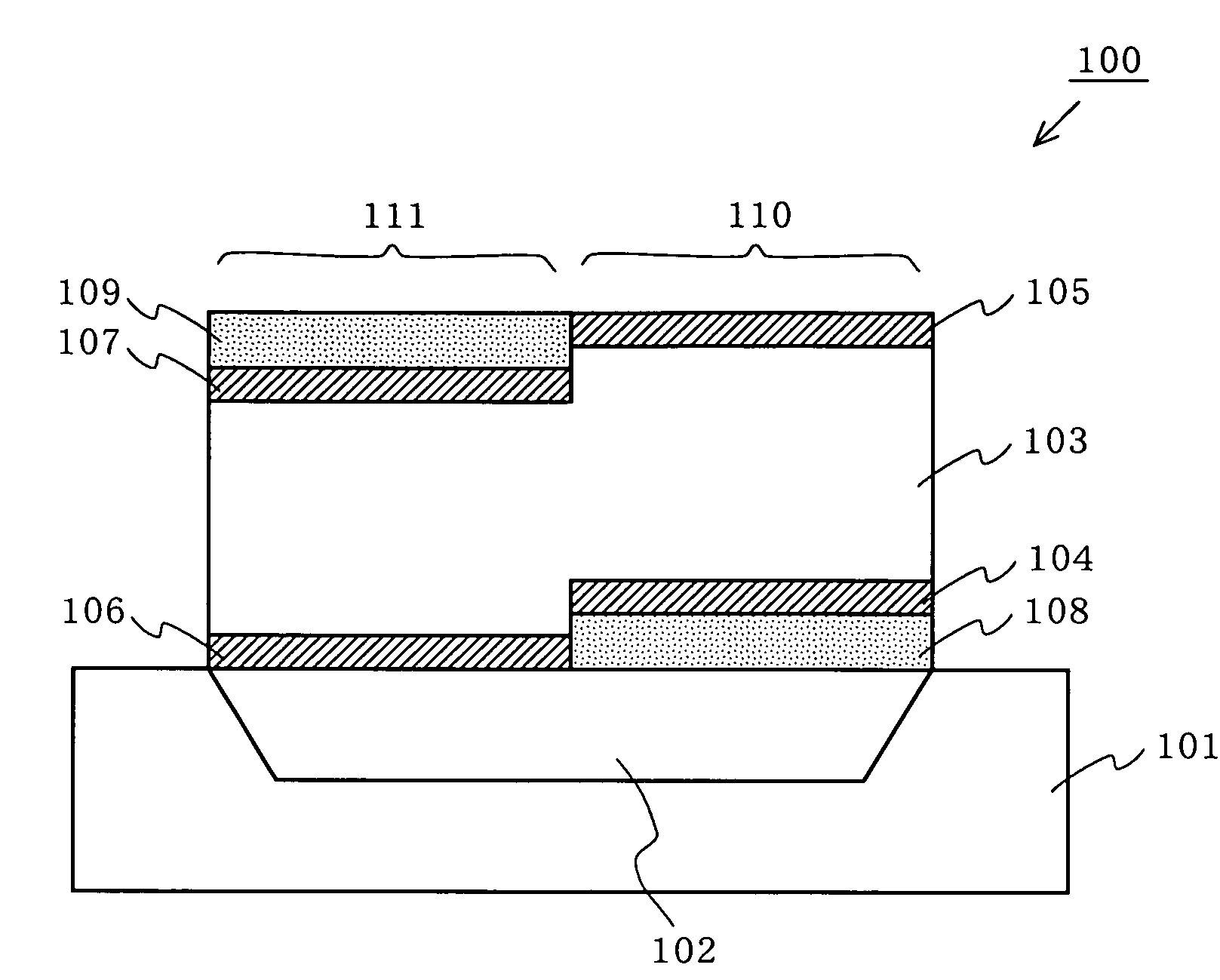
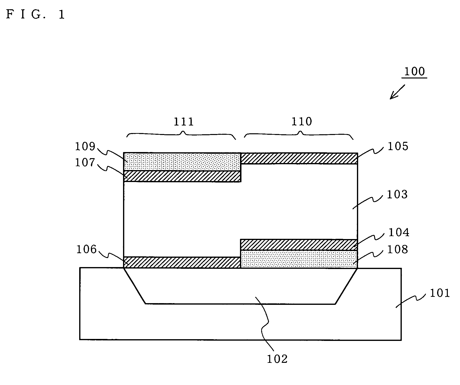
[0057]FIG. 1 is a cross-sectional view of a coupled FBAR filter 100 according to a first embodiment of the present invention. As shown in FIG. 1, the coupled FBAR filter 100 includes a substrate 101, a cavity 102, a piezoelectric thin film 103, a first lower electrode 104, a first upper electrode 105, a second lower electrode 106, a second upper electrode 107, a first insulator 108, and a second insulator 109.

[0058]The first and second lower electrodes 104 and 106, and the first and second upper electrodes 105 and 107, are formed of, for example, molybdenum (Mo). The piezoelectric thin film 103 is formed of a piezoelectric material such as, for example, aluminum nitride (AlN). The first and second insulators 108 and 109 are formed of, for example, silicon dioxide (SiO2).

[0059]First, a structure of the coupled FBAR filter 100 according to the first embodiment will be described in detail.

[0060]The first lower electrode 104, the first upper electrode 105, and a part of the piezoelectri...

second embodiment

[0073]In the first embodiment, the coupled FBAR filter suitable to a circuit (FIG. 3) in which the four electrodes 104 through 107 need to be insulated from one another is described. As shown in FIG. 5 and FIG. 8, a circuit in which two electrodes are grounded is often used for a coupled FBAR filter. In such a circuit, the two grounded electrodes do not need to be insulated. In other words, the feature 2 or the feature 3 does not need to be considered.

[0074]In a second embodiment, a coupled FBAR filter suitable to the circuit shown in FIG. 5 will be described.

[0075]FIG. 6 is a cross-sectional view of a coupled FBAR filter 300 according to the second embodiment of the present invention. As shown in FIG. 6, the coupled FBAR filter 300 includes a substrate 101, a cavity 102, a piezoelectric thin film 103, a lower electrode 304, a first upper electrode 105, a second upper electrode 107, and an insulator 109. As can be seen from FIG. 6, the second embodiment is different from the first e...

third embodiment

[0079]In a third embodiment, a coupled FBAR filter suitable to the circuit shown in FIG. 8 will be described.

[0080]FIG. 9 is a cross-sectional view of a coupled FBAR filter 500 according to the third embodiment of the present invention. As shown in FIG. 9, the coupled FBAR filter 500 includes a substrate 101, a cavity 102, a piezoelectric thin film 103, a first lower electrode 104, a second lower electrode 106, an upper electrode 505, and an insulator 108. As can be seen from FIG. 9, the third embodiment is different from the first embodiment in the structure of the upper electrode 505. Elements having an identical function to those of the first embodiment bear the same reference numerals thereto and the descriptions thereof will be omitted.

[0081]The first lower electrode 104, a part of the upper electrode 505, and a part of the piezoelectric thin film 103 interposed between these electrodes form a first input / output vibration portion 110. The second lower electrode 106, a part of t...


PUM


Abstract

A coupled FBAR filter 100 includes first and second input / output vibration portions 110 and 111 respectively including first and second lower electrodes 104 and 106, first and second upper electrodes 105 and 107, and a piezoelectric thin film 103 interposed therebetween; and a cavity 102 for commonly guaranteeing vibrations of the first and second input / output vibration portions 110 and 111 so as to couple the vibrations. The first and second input / output vibration portions 110 and 111 are located adjacently in contact with each other with a step therebetween, such that the first and second lower electrodes 104 and 106 are not electrically connected to each other and such that the first and second upper electrodes 105 and 107 are not electrically connected to each other. Insulators 108 and 109 are provided in the vicinity of the step.

Description

BACKGROUND OF THE INVENTION[0001]1. Field of the Invention[0002]The present invention relates to a coupled FBAR filter usable for a radio frequency circuit of a wireless device or the like, and more particularly to an FBAR filter using a plurality of modes, and a duplexer and a communication device including the same.[0003]2. Description of the Background Art[0004]Conventionally, filters mounted on wireless communication devices such as cellar phones and the like include dielectric filters, laminated filters and acoustic filters. Known acoustic filters include a monolithic crystal filter (MCF) using a plurality of modes of a bulk wave and a surface acoustic wave filter (SAW filter). Recently, filters are required to have a smaller size, to provide a higher performance and to be usable at a higher frequency. As a device for fulfilling these requirements, a film bulk acoustic resonator filter (FBAR filter) using a bulk wave of a piezoelectric thin film has been developed.[0005]A conve...

Claims


Application Information

Patent Timeline
Patent Type & Authority Patents(United States)
IPC IPC(8): H03H9/00
CPCH03H9/564H03H9/0207
Inventor IWASAKI, TOMOHIRONAKATSUKA, HIROSHIONISHI, KEIJINAKAMURA, HIROYUKI
Owner PANASONIC CORP
Why Eureka
Try Eureka