Elastic wave filter device and antenna duplexer using same

a filter device and elastic wave technology, applied in the direction of impedence networks, electrical devices, piezoelectric/electrostrictive/magnetostrictive devices, etc., can solve the problems of elastic wave filter devices, ) may exhibit degradation in out-of-band attenuation, etc., to increase isolation characteristics and favorable filter characteristics

Active Publication Date: 2012-12-13
SKYWORKS PANASONIC FILTER SOLUTIONS JAPAN
View PDF6 Cites 13 Cited by
  • Summary
  • Abstract
  • Description
  • Claims
  • Application Information

AI Technical Summary

Benefits of technology

[0010]This configuration prevents influence of noise components passing through the ground electrode, thereby providing favorable filter characteristics.
[0011]An antenna duplexer of the present invention uses elastic wave filter devices of the present invention as the transmission filter and the receiving filter, and shares the antenna terminal. This configuration allows increasing the isolation characteristics.

Problems solved by technology

However, even if the electrode finger pattern of an IDT is optimized to increase attenuation of the elastic wave element itself out of the band, an elastic wave filter device that is a product finished by containing the elastic wave elements into a package (not shown) may exhibit degradation in out-of-band attenuation.

Method used


Image

  • Elastic wave filter device and antenna duplexer using same
  • Elastic wave filter device and antenna duplexer using same
  • Elastic wave filter device and antenna duplexer using same

Examples


first exemplary embodiment

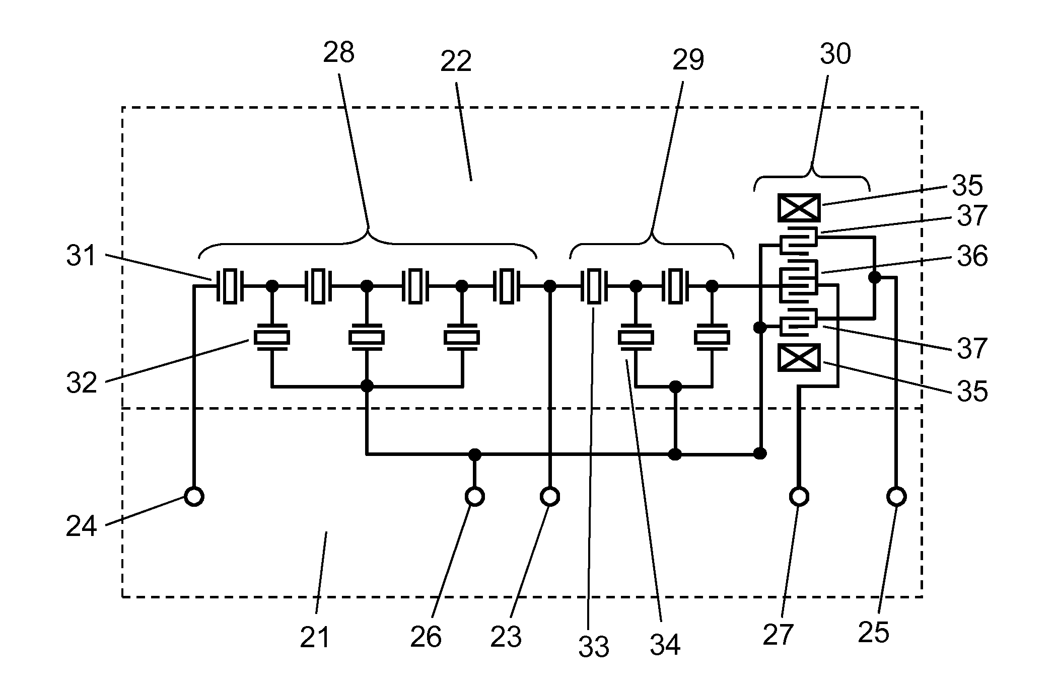
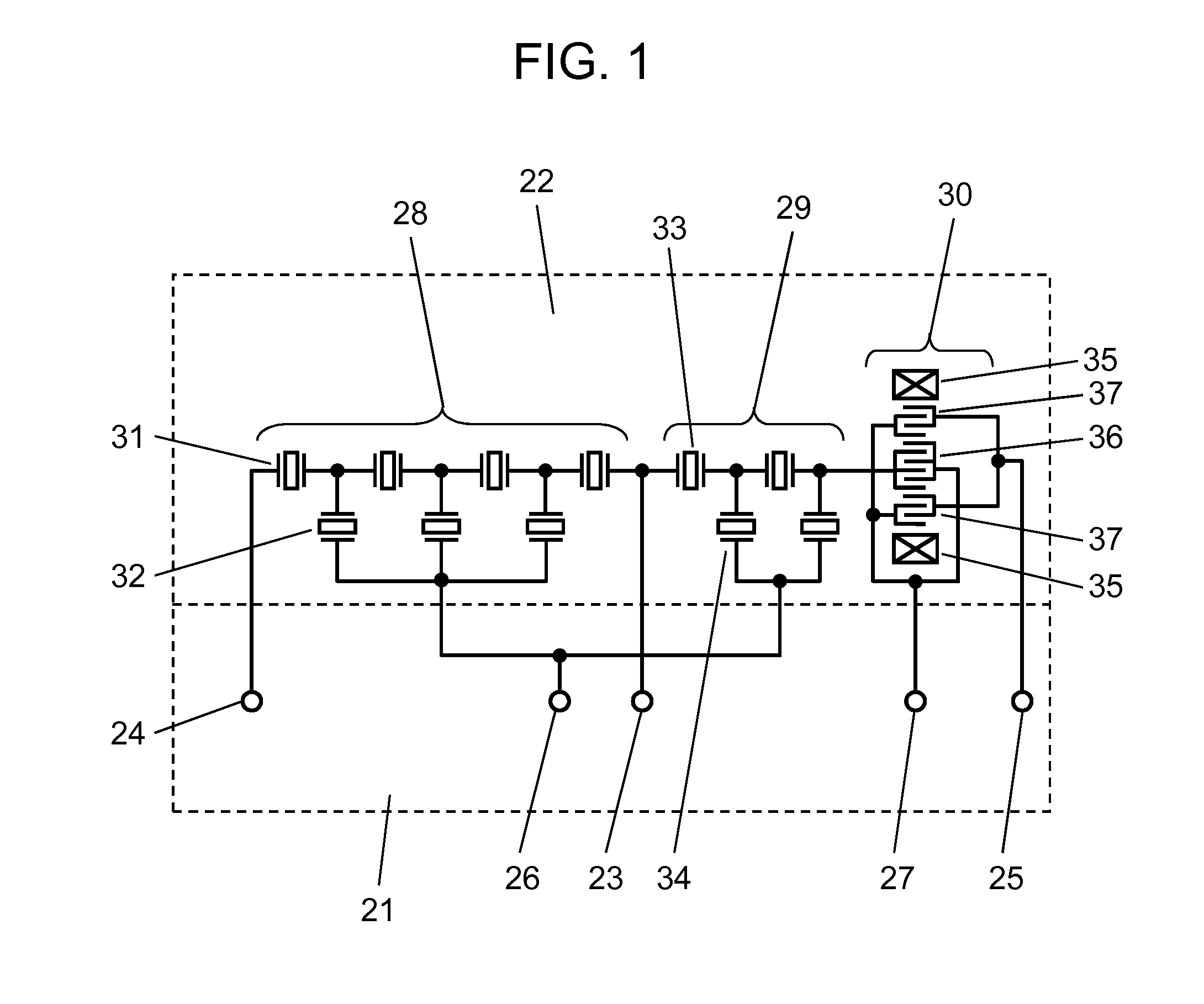
[0024]FIG. 1 is a circuit diagram of an elastic wave filter device according to the first exemplary embodiment of the present invention. The elastic wave filter device includes panel 21 made of a ceramic substrate; and chip 22 made of a single-crystal piezoelectric substrate, attached onto panel 21. Panel 21 includes common terminal 23, transmission-side terminal 24, receiving-side terminal 25, first ground electrode 26, second ground electrode 27, and wirings connecting these terminals and electrodes. Chip 22 includes, on its surface, first ladder-type elastic wave filter 28 forming the transmission-side filter;

[0025]and second ladder-type elastic wave filter 29 and longitudinally coupled resonator-type elastic wave filter 30 both forming the receiving-side filter. Filters 28, 29, and 30 are formed of elastic wave elements (not shown).

[0026]Filter 28 includes series arm resonator 31 and parallel arm resonator 32. One end of filter 28 is connected to common terminal 23, and the othe...

second exemplary embodiment

[0042]FIG. 6 is a circuit diagram of an elastic wave filter device according to the second exemplary embodiment of the present invention. FIG. 7 is a common-mode passing characteristic diagram of the device.

[0043]In FIG. 6, a component common to that of FIG. 1 is given the same reference mark, and its description is omitted. In this embodiment, longitudinally coupled resonator-type elastic wave filter 38 is of an imbalance / balance conversion type, and receiving-side terminal 39 is formed of a pair of balanced terminals. That is, the elastic wave filter device of this embodiment is formed by connecting ladder-type elastic wave filters 28 and 29 with imbalance / balance conversion type longitudinally coupled resonator-type elastic wave filter 38.

[0044]In FIG. 7, the solid line represents the common-mode passing characteristics between receiving-side terminals 39 of the elastic wave filter device of the embodiment. The broken line in FIG. 7 is a comparative example, representing the pass...


PUM


Abstract

An elastic wave filter device includes a longitudinally coupled resonator-type elastic wave filter formed on a piezoelectric substrate; and a ladder-type elastic wave filter connected to the resonator-type elastic wave filter. The resonator-type filter includes an input IDT and an output IDT. The ladder-type filter includes a series arm resonator and a parallel arm resonator. A first ground electrode connected to the parallel arm resonator is electrically separated from a second ground electrode connected to at least one of the input IDT and the output IDT.

Description

TECHNICAL FIELD[0001]The present invention relates to an elastic wave filter device mainly used for mobile communication equipment and to an antenna duplexer using the elastic wave filter.BACKGROUND ART[0002]In recent years, antenna duplexers have been widely used that separate transmitting waves and receiving waves using an elastic wave filter device in the antenna circuit of a mobile phone. FIG. 11 is a circuit diagram of a conventional elastic wave filter device. The device includes panel 1 made of a ceramic substrate and chip 2 attached onto panel 1. Panel 1 includes common terminal 3, transmission-side terminal 4, receiving-side terminal 5, ground electrode 6, and wirings connecting these terminals. Chip 2 made of a single-crystal piezoelectric substrate, includes, on its surface, first ladder-type elastic wave filter 7 forming the transmission-side filter; and second ladder-type elastic wave filter 8 and longitudinally coupled resonator-type elastic wave filter 9 both forming ...

Claims


Application Information

Patent Timeline
Patent Type & Authority Applications(United States)
IPC IPC(8): H03H9/72H03H9/64
CPCH03H9/725
Inventor TSURUNARI, TETSUYAFUJIWARA, JOJINAKAMURA, HIROYUKI
Owner SKYWORKS PANASONIC FILTER SOLUTIONS JAPAN
Why Eureka
Try Eureka