Radio frequency module

Active Publication Date: 2017-03-16
MURATA MFG CO LTD
View PDF0 Cites 14 Cited by
  • Summary
  • Abstract
  • Description
  • Claims
  • Application Information

AI Technical Summary

Benefits of technology

[0023]According to various preferred embodiments of the present invention, the propagation path to further improve the filter characteristics is able to be provided with a simple configuration without deteriorating the attenuation characteristics outside the frequency band of the transmission filter. Therefore, the attenuation characteristics of an RF signal outside the frequency band of the transmission signal are able to be improved without increasing the size of the radio fr

Problems solved by technology

However, in some cases, the RF signal outside the pass band cannot be attenuated to a desired value with only the filter unit 503.
Accordingly, a pro

Method used


Image

  • Radio frequency module
  • Radio frequency module
  • Radio frequency module

Examples


first preferred embodiment

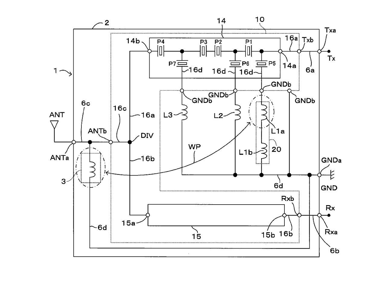
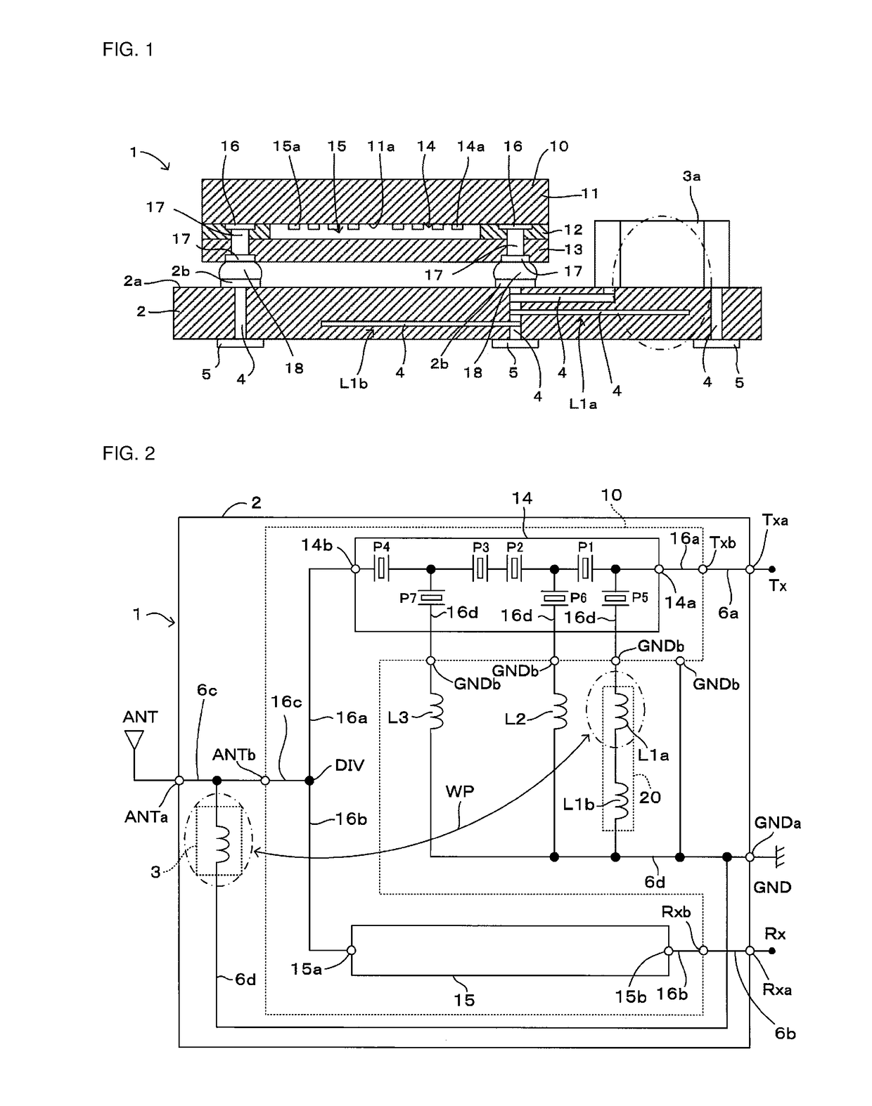
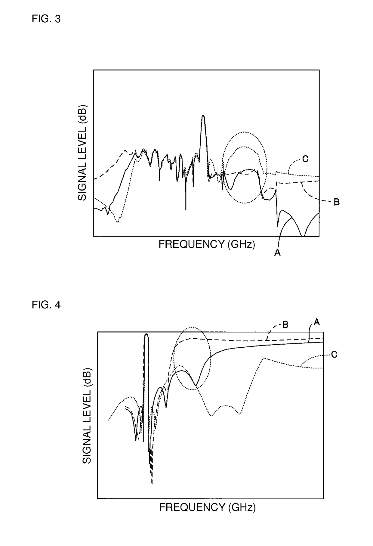
[0037]A first preferred embodiment of a radio frequency module according to the present invention will be described below with reference to FIGS. 1 to 4. It is to be noted that, in FIGS. 1 and 2, only principal components of preferred embodiments of the present invention are illustrated, and other components are omitted for the sake of simplifying the explanation. Also, in other drawings referred to in later descriptions, only the principal components of preferred embodiments of the present invention are illustrated as in FIGS. 1 and 2, while explanation thereof is omitted in the description of the other drawings.

[0038]The radio frequency module 1 illustrated in FIGS. 1 and 2 is mounted on a motherboard of a communication portable terminal, e.g., a cellular phone or a portable information terminal. In this preferred embodiment, the radio frequency module 1 includes a duplexer 10 including a transmission filter 14 and a reception filter 15, a module substrate 2, a matching circuit 3,...

second preferred embodiment

[0082]A second preferred embodiment of the radio frequency module according to the present invention will be described below with reference to FIGS. 5 and 6.

[0083]This preferred embodiment is different from the first preferred embodiment in that, as illustrated in FIGS. 5 and 6, the wiring electrode 4 defining the first inductor L1a is located just under the duplexer 10, and that the first inductor L1a and the intra-duplexer transmission path 16a or the intra-duplexer reception path 16b are connected to each other in radio frequencies through electromagnetic coupling, such that the propagation path WP is provided. Furthermore, between the first inductor L1a and the second inductor L1b, a shielding ground electrode 30 defined by the wiring electrode 4 connected to the ground terminal GNDa of the module substrate is located between the first inductor L1a and the second inductor L1b to suppress or prevent electromagnetic coupling between the first inductor L1a and the second inductor L...

third preferred embodiment

[0085]A third preferred embodiment of the radio frequency module according to the present invention will be described below with reference to FIG. 7. FIG. 7 is a plan view of a (principal) portion of the module substrate 2 of the radio frequency module 1 when viewed from the side facing the mounting surface 2a.

[0086]This preferred embodiment is different from the first preferred embodiment in that, as illustrated in FIG. 7, a chip-type surface mounted component 7 defining the first inductor L1a and the chip-type surface mounted component 3a (inductor) defining the matching circuit 3 are mounted to the mounting surface 2a of the module substrate 2, and in that the surface mounted component 7 and the surface mounted component 3a are adjacent to each other. Moreover, as illustrated in FIG. 7, the surface mounted component 7 is positioned so as not to be overlapped with a region in which the wiring electrode 4 defining the second inductor L1b is arranged, when viewed in a plan view. Th...


PUM


Abstract

A radio frequency module includes a transmission terminal, a transmission filter connected to the transmission terminal, a common terminal, a reception filter which is connected to the common terminal, a reception terminal, a branch point to which the common terminal, the transmission filter, and the reception filter are connected, a transmission path connecting the transmission terminal and the branch point, a reception path connecting the reception terminal and the branch point, a common path connecting the common terminal and the branch point, a matching circuit connected to the common path, and an inductor circuit that includes a first inductor that defines a propagation path through electromagnetic coupling to at least one of the transmission path, the common path, the matching circuit, and the reception path, and a second inductor that is positioned so as not to be electromagnetically coupled to the transmission path, the common path, the matching circuit, or the reception path.

Description

CROSS REFERENCE TO RELATED APPLICATIONS[0001]This application claims the benefit of priority to Japanese Patent Application No. 2015-034723 filed Feb. 25, 2015 and is a Continuation Application of PCT Application No. PCT / JP2016 / 053303 filed on Feb. 4, 2016. The entire contents of each application are hereby incorporated herein by reference.BACKGROUND OF THE INVENTION[0002]1. Field of the Invention[0003]The present invention relates to a radio frequency module that demultiplexes a transmission signal and a reception signal.[0004]2. Description of the Related Art[0005]A radio frequency module including a filter circuit has been previously provided. For example, a filter circuit 500 illustrated in FIG. 12 is mounted to a radio frequency module (see, e.g., Japanese Unexamined Patent Application Publication No. 2012-109818 (Paragraphs 0019 to 0023, FIG. 1, Abstract, etc.)). The filter circuit 500 includes a filter unit 503 connected between an input terminal 501 and an output terminal 50...

Claims


Application Information

Patent Timeline
IPC IPC(8): H03H7/46H03H7/38H03H9/54H03H9/70H03H9/64H03H7/01H03H9/72
CPCH03H7/463H03H7/0138H03H7/38H03H9/54H03H9/706H03H9/64H03H9/725H03H7/09H03H9/0542H03H9/0566H04B1/0458H04B1/18H04B1/52H04B1/525
Inventor SUGAYA, YUKITERUMIZOGUCHI, SHINYA
Owner MURATA MFG CO LTD
Why Eureka
Try Eureka