Secondary surveillance radar and its interrogation transmission method

a second-generation radar and transmission method technology, applied in the field of second-generation surveillance radar, can solve the problems of deterioration in the detection rate of a conventional atcrbs transponder, inability of ssr to schedule the transactions, and lengthening the time required for transactions, so as to secure the time for transmitting other interrogations

Inactive Publication Date: 2008-08-05
KK TOSHIBA
View PDF6 Cites 23 Cited by
  • Summary
  • Abstract
  • Description
  • Claims
  • Application Information

AI Technical Summary

Benefits of technology

[0010]An object of the present invention is to provide a secondary surveillance radar and its interrogation transmission method capable of securing the time for transmitting other interrogations by reducing interrogations toward an azimuth having a small possibility of receiving of responses.
[0012]According to a second aspect of the present invention, there is provided an interrogation transmission method of a secondary surveillance radar for dividing an interrogation repetition cycle into two, which are an all-call period to perform transactions for a transponder of an air traffic control radar beacon system (ATCRBS) and a mode S and a roll-call period to perform selective transactions for a transponder of the mode S and having a function to vary angle ranges for transmitting the interrogations in accordance with the prediction angle ranges of targets in the roll-call period, comprising: a first step of comparing a beam-width of an antenna with the prediction angle ranges; a second step of continuing selective interrogations at every roll-call period if the prediction angle ranges are narrower than the beam-width in the comparison in the first step; and a third step of thinning out transmissions of selective interrogations at every roll-call period with prescribed intervals if the prediction angle ranges are wider than the beam-width in the comparison in the first step.

Problems solved by technology

If the data-link protocol is frequently used in the future, there will be a method for simply lengthening the time length of the roll-call period; however, deterioration in detection rate of a conventional ATCRBS transponder will be caused (because of reduction in the number of responses).
And there is a possibility of an occurrence of the problem that the SSR cannot schedule the transactions for the target in a relatively short range within a beam-width of an antenna (generally, indicating an angle range of beam center azimuth ±1.250°), because the SSR schedules transactions prior to a long distance target in the case of congestion of targets at long distances within the corresponding beam.
Furthermore, in the case of use of the data-link protocol, since the length of the interrogation and the length of response become longer than those for surveillance, the time required for the transactions is lengthened and the possibility of an occurrence of an event which cannot be scheduled by the SSR is further increased.

Method used


Image

  • Secondary surveillance radar and its interrogation transmission method
  • Secondary surveillance radar and its interrogation transmission method
  • Secondary surveillance radar and its interrogation transmission method

Examples


Embodiment Construction

[0024]At first, prior to an explanation of an embodiment of the present invention, a brief of an SSR mode S and problems of a present interrogation transmission system will be explained specifically.

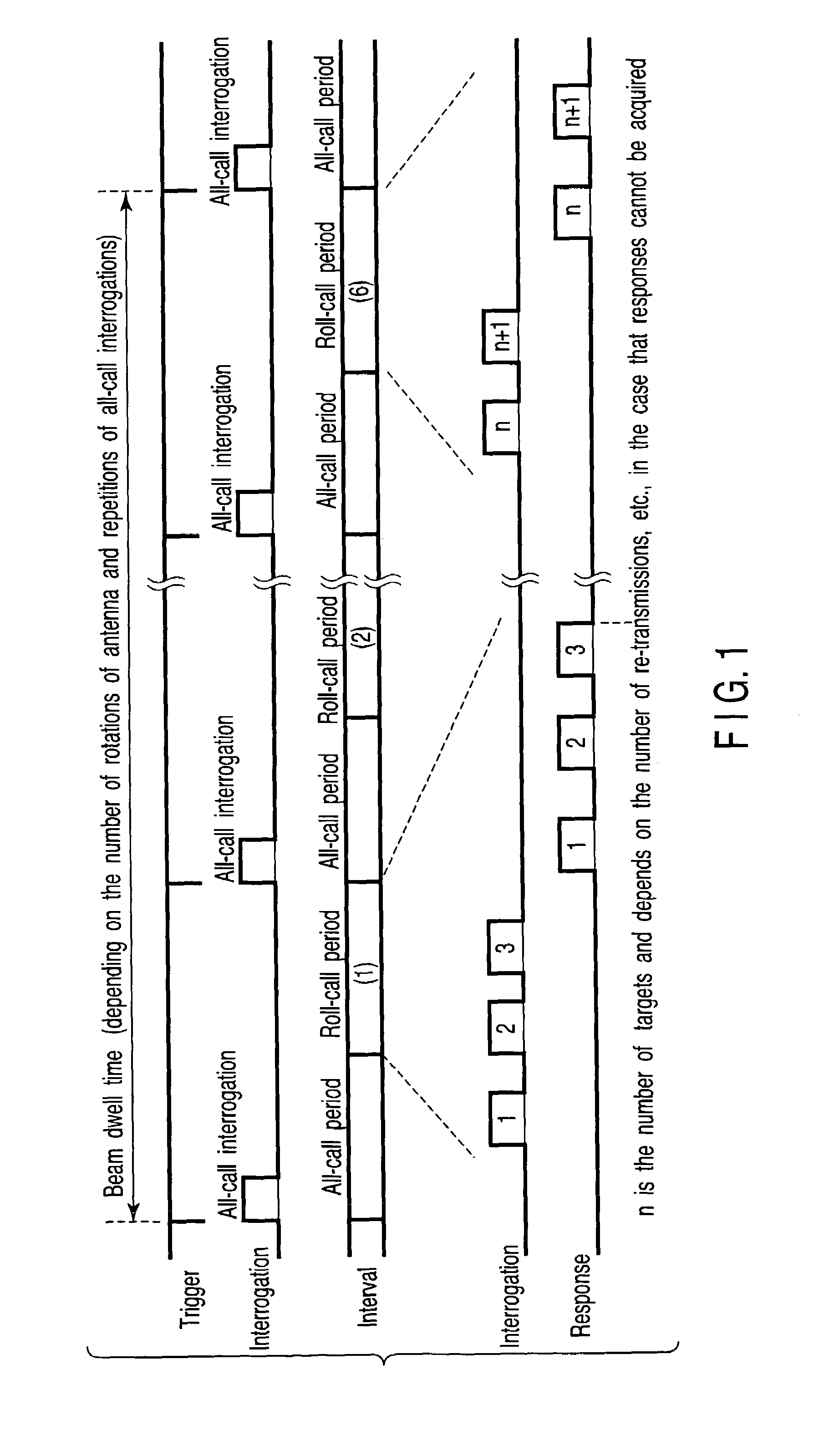
[0025]FIG. 1 is an operation timing view for explaining a brief of an SSR mode S to which the present invention is adopted. In the SSR mode S, as shown in FIG. 1, an SSR divides a beam dwell time into one or more scheduling periods by using a trigger signal with a constant cycle. And, the SSR divides each scheduling period into two, which are an all-call period (period to capture mode S transponder and ATCRBS transponder) and a roll-call period (period to perform selective interrogation and response to mode S transponder) to transmit an all-call interrogation signal in accordance with a trigger signal in each scheduling period. Thereby, the SSR captures the target within an antenna beam. Here, in FIG. 1, “n” indicates the number of targets. When the SSR cannot capture a response, it perf...


PUM


Abstract

An interrogation transmission method of a secondary surveillance radar compares prediction angle ranges for transmitting interrogations with a beam-width of an antenna, and transmits the interrogations at every roll-call period if the prediction angle ranges for transmitting interrogations are narrower than the beam-width of the antenna. In contrast, if the prediction angle ranges for transmitting the interrogations are wider than the beam-width of the antenna, the radar respectively sets a period to transmit the interrogations and a period not to transmit the interrogations until responses can be received, and transmits interrogations at every roll-call period after the responses can be received (even if a receiving error or downlink occurs).

Description

CROSS-REFERENCE TO RELATED APPLICATIONS[0001]This application is based upon and claims the benefit of priority from prior Japanese Patent Application No. 2004-266363, filed Sep. 14, 2004, the entire contents of which are incorporated herein by reference.BACKGROUND OF THE INVENTION[0002]1. Field of the Invention[0003]The present invention relates to secondary surveillance radar (SSR) for surveying a target such as an airplane equipped with a mode S transponder and an air traffic control radar beacon system (ATCRBS) transponder.[0004]2. Description of the Related Art[0005]An SSR mode S is a radar system to capture a variety of items of information owned by an airplane by transmitting an interrogation from a beam antenna of a device to a transponder mounted on a target such as an airplane and receiving a response (cf., for example, documents “ISBN0-89006-292-7”, “Revision Radar Technique”, issued by Institute of electronics, Information and Communication Engineers, 1996, P. 227-233”). ...

Claims


Application Information

Patent Timeline
Patent Type & Authority Patents(United States)
IPC IPC(8): G01S13/74G01S13/00
CPCG01S13/781G01S13/765
Inventor KUJI, YOSHINORIAOKI, YOSHIROUOOTOMO, HISASHI
Owner KK TOSHIBA
Why Eureka
Try Eureka