Optical fiber having a low polarization mode dispersion and process and apparatus for producing it

a technology of optical fiber and dispersion mode, which is applied in the field of process for producing a low polarization mode dispersion optical fiber, can solve the problems of pulse spreading, birefringence being detrimental, and the symmetry of the core cylindrical may be disrupted

Inactive Publication Date: 2008-08-05
PRYSMIAN CAVI E SISTEMI ENERGIA
View PDF15 Cites 3 Cited by
  • Summary
  • Abstract
  • Description
  • Claims
  • Application Information

AI Technical Summary

Benefits of technology

[0023]The Applicant has found that, by spinning the fiber unidirectionally during drawing, and then de-twisting the fiber in a direction opposite that of the elastic torsion caused by spinning so as to control the elastic to...

Problems solved by technology
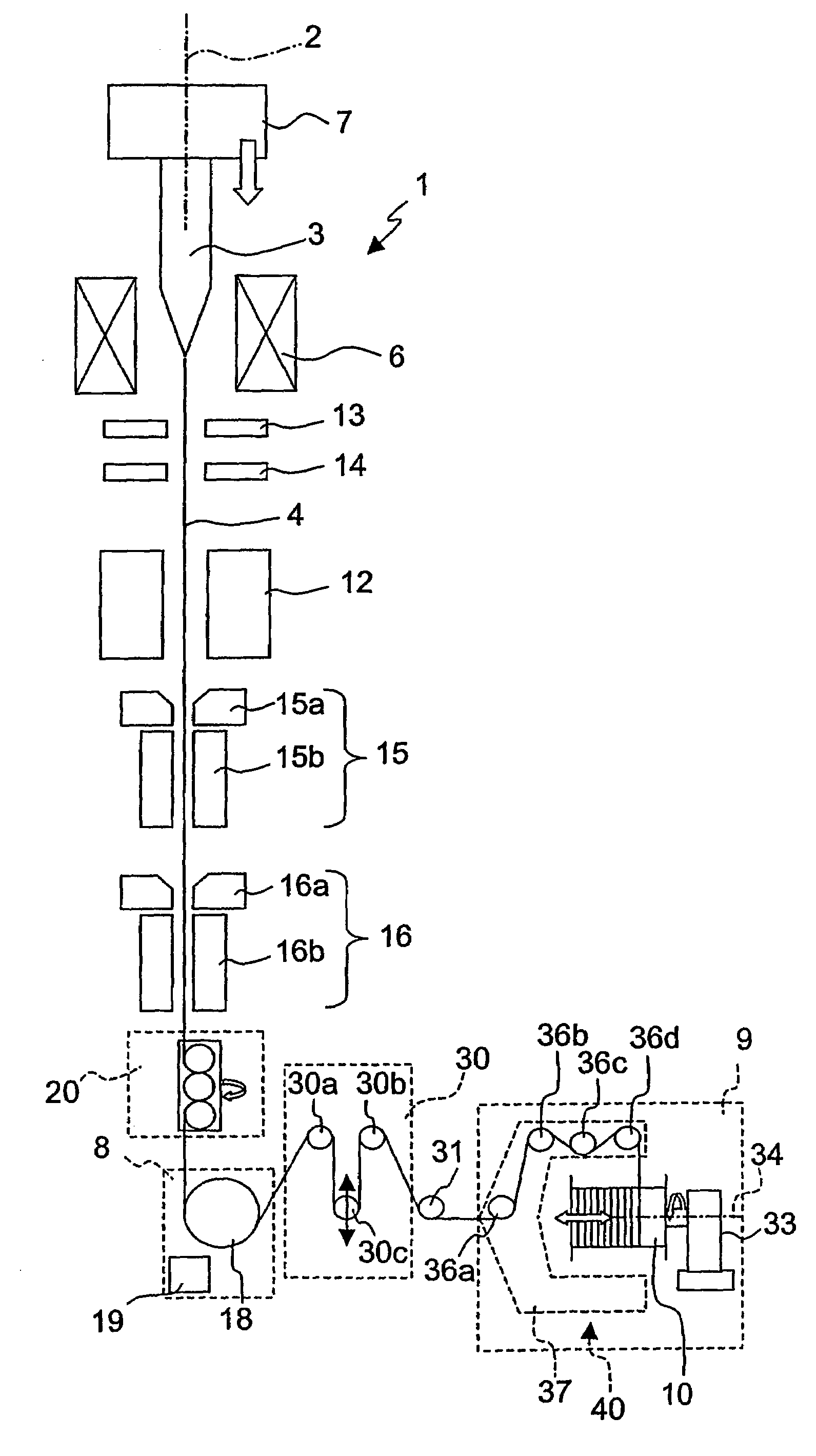
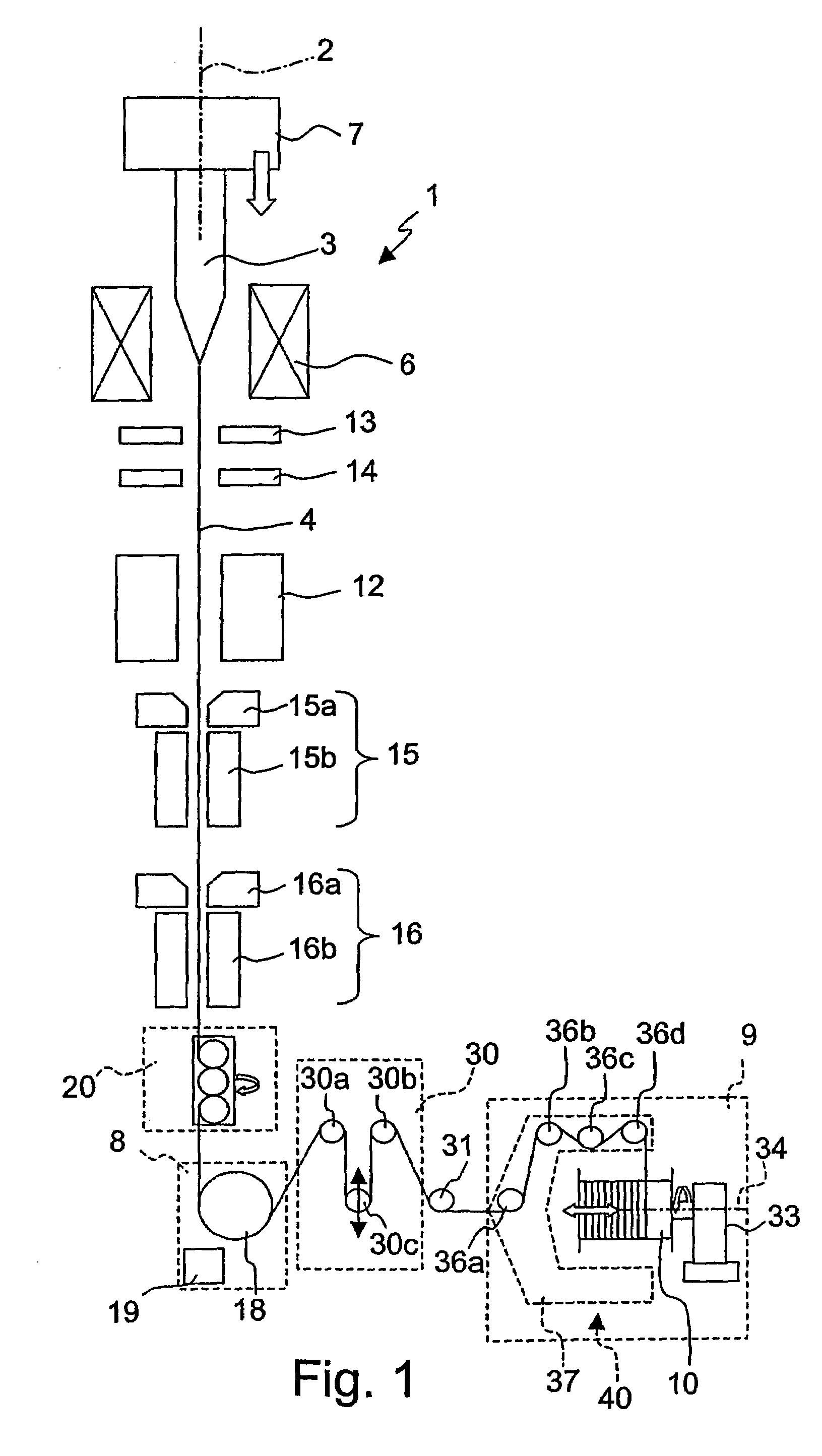
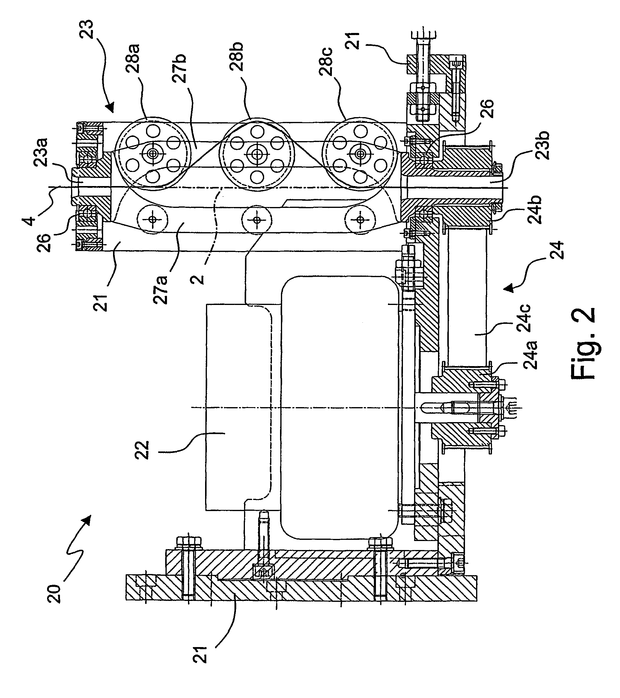
However, in real optical fibers the core cylindrical symmetry may be disrupted due to shape defects or non-uniform stresses.
However, in ordinary (i.e. non-polarization-preserving) fibers, birefringence is detrimental.
In fact, when pulsed signals are transmitted into an optical fiber, the birefringence is a potential cause of pulse spreading, since the two polarization components excited by the pulses travel at different group velocities (i.e. become dispersed).
Typically, the phenomenon of PMD leads to a limitation of the width of the signal transmission band and, consequently, a degradation of the performance of the optical fibers along which the aforesaid signals are transmitted.
This phenomenon is therefore undesirable in systems of signal transmission along optical fibers, especially in those operating over long distances, in which it is necessary to minimize any form of attenuation or dispersion of the signals to guarantee high performances in transmission and reception.
International patent application WO 97/26221 observes that the reduction in PMD produced by spinning is proportional to the spin rate, that very high spin rates are generally requir...

Method used


Image

  • Optical fiber having a low polarization mode dispersion and process and apparatus for producing it
  • Optical fiber having a low polarization mode dispersion and process and apparatus for producing it
  • Optical fiber having a low polarization mode dispersion and process and apparatus for producing it

Examples


examples

[0111]In a first experiment, the Applicant has compared the PMD of a unspun fiber with the PMD of a fiber spun at 7.3 turns / m. Two corresponding fibers of 10 km length, consistent with the ITU-T G.652 specification, were drawn from the same preform (obtained with the OVD deposition technique). The experiment was carried out at a typical drawing speed.

[0112]After measuring the residual twist of the spun fiber with the above-described technique, the fiber was cut in 1-km spans associated with different residual twists. In practice, a first 1-km span was wound on a smaller bobbin with a predetermined detwist, then the fiber was cut and a second 1-km span was wound on another smaller bobbin with a different detwist, and so on. The PMD of the different spans was then measured.

[0113]FIG. 7a shows the PMD of six 1-km spans of spun fiber having different residual twists, compared to the PMD of the unspun fiber. The Figure shows the improvement obtainable in terms of PMD by twisting the fibe...


PUM

PropertyMeasurementUnit
Intrinsic viscosityaaaaaaaaaa

Abstract

An apparatus for producing a low-PMD optical fiber having a furnace for melting a lower portion of an optical preform; a traction device for pulling an optical fiber from the lower portion of an optical preform; a spinning device for imparting a substantially constant and unidirectional spin to the optical fiber as it is pulled, which causes the fiber to undergo an elastic torsion; a winding device for winding the optical fiber onto a reel; and a twisting device for imparting to the spun optical fiber a unidirectional twist in a direction opposite the elastic torsion, so as to control the residual twist in the optical fiber. A process for producing the fiber, an optical fiber and a cable are also provided.

Description

CROSS REFERENCE TO RELATED APPLICATION[0001]This application is a national phase application based on PCT / EP2003 / 010517, filed Sep. 22, 2003, the content of which is incorporated herein by reference.BACKGROUND OF THE INVENTION[0002]1. Field of the Invention[0003]The present invention relates to a process for producing a low-polarization mode dispersion optical fiber.[0004]2. Description of the Related Art[0005]Optical signals transmitted through single-mode optical fibers comprise two orthogonal polarization modes (typically denoted TE and TM) that, in case of a fiber with a perfectly cylindrical core of uniform diameter, propagate at a common velocity. However, in real optical fibers the core cylindrical symmetry may be disrupted due to shape defects or non-uniform stresses. As a result, a phase difference can accumulate between the two modes, and the fiber is said to show “birefringence”. In particular, the birefringence introduced by shape and stress asymmetry is known as “intrin...

Claims


Application Information

Patent Timeline
IPC IPC(8): G02B6/44B65H49/02B65H55/00C03B37/027C03B37/03C03B37/12G02B6/02
CPCB65H49/02C03B37/02745C03B37/032C03B37/12G02B6/02285C03B2203/20C03B2203/36C03B2205/06C03B2203/19
Inventor ROBA, GIACOMO STEFANOSARCHI, DAVIDETRAVAGNIN, MARTINODEBUT, ALEXIS
Owner PRYSMIAN CAVI E SISTEMI ENERGIA
Why Eureka
Try Eureka