
Methods for modifying ovality of optical fiber preforms

a technology of optical fiber and preforms, applied in the field of optical fiber fabrication, can solve the problems of undesirable preform ovality, difficult to overcome the difficulties of their manufacture, and the preform generated by this process often suffers from ovality, so as to reduce the ovality of the preform core, reduce the ovality, and reduce the ovality

Inactive Publication Date: 2011-03-10
FITEL USA CORP
View PDF16 Cites 0 Cited by
  • Summary
  • Abstract
  • Description
  • Claims
  • Application Information

AI Technical Summary

Benefits of technology

The present invention provides methods for reducing the ovality of optical fiber preforms during the creation process. The methods involve altering the outer diameter of the starting tube or etching the core rod after it is formed. These methods help to reduce the PMD (polarization-related dispersion) of optical fibers drawn from the preform. Additionally, the invention also includes a method of measuring the ovality of the starting tube or core rod and rotating the core rod to further reduce ovality. Overall, the invention improves the quality of optical fibers and enhances the efficiency of the manufacturing process.

Problems solved by technology

Despite their advantages, however, difficulties in their manufacture must be overcome in order for lengthy, high-yield and error-free optical fiber to be produced in mass.
Although the generation of preforms by the method described above are commonly utilized in optical fiber manufacturing, preforms generated by this process often suffer from ovality; that is, the preforms do not necessarily have a circular cross section throughout their entire length.
Preform ovality is undesirable because it changes and more often increases the Polarization Mode Dispersion (PMD) of optical fiber.
PMD limits the transmission capacity of optical communication systems by creating inter-symbol interference.

Method used


Image

  • Methods for modifying ovality of optical fiber preforms
  • Methods for modifying ovality of optical fiber preforms
  • Methods for modifying ovality of optical fiber preforms

Examples


Embodiment Construction

[0024]The present inventions now will be described more fully hereinafter with reference to the accompanying drawings, in which some, but not all embodiments of the invention are shown. Indeed, these inventions may be embodied in many different forms and should not be construed as limited to the embodiments set forth herein; rather, these embodiments are provided so that this disclosure will satisfy applicable legal requirements. Like numbers refer to like elements throughout.

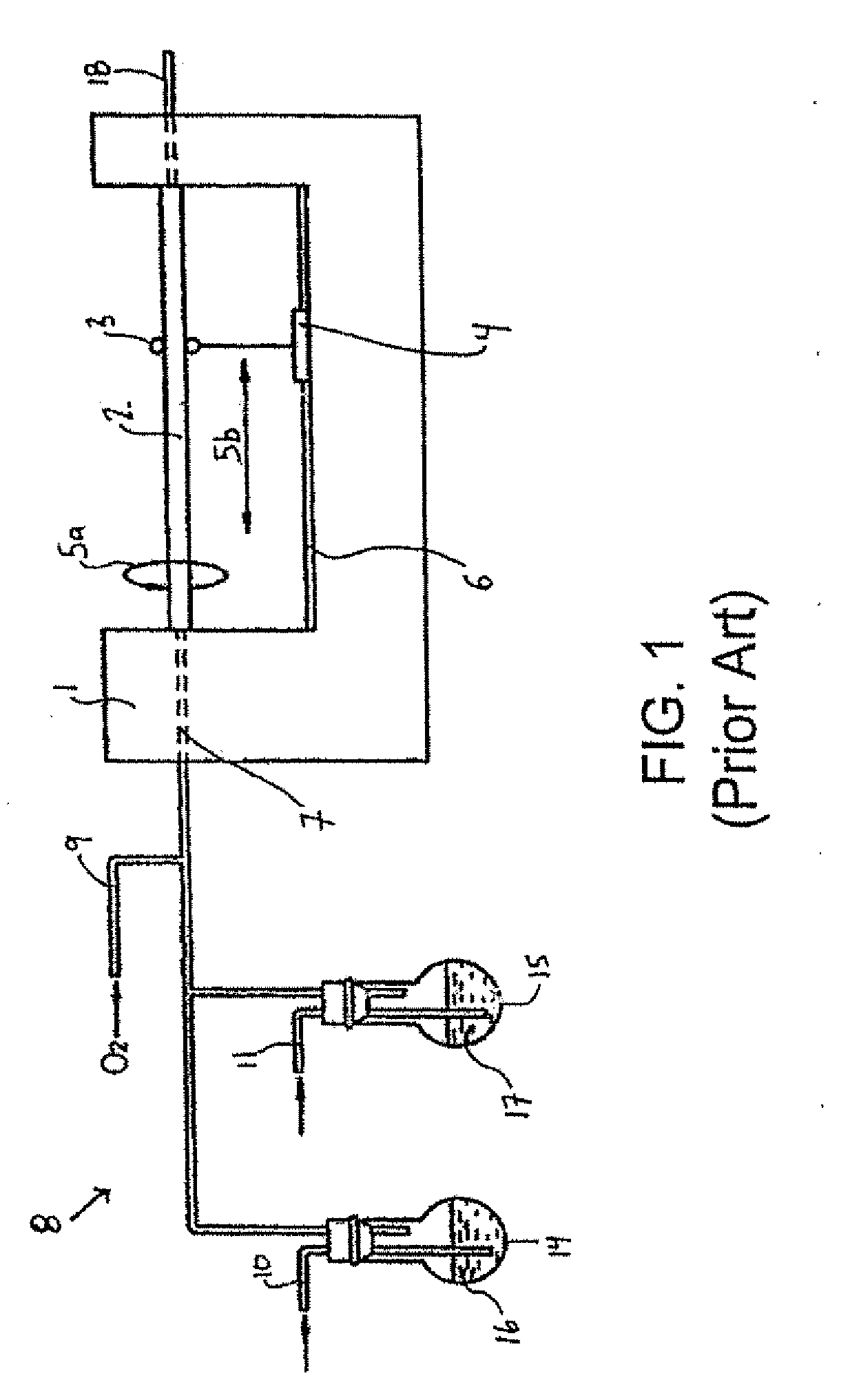
[0025]FIG. 1 shows an apparatus suitable for a MCVD process, as is known in the prior art. The apparatus includes a shelf 1 which supports a starting tube 2 and a heating means 4 that applies heat to a heating zone 3 of the starting tube 2. The starting tube 2 rotates, for example, in the direction indicated by an arrow 5a, and the heating means 4 reciprocates in the direction indicated by an arrow 5b by a moving member in track 6, so that the heating zone 3 is shifted along the entire starting tube 2 while the...


PUM

PropertyMeasurementUnit
shapeaaaaaaaaaa
lengthaaaaaaaaaa
diameteraaaaaaaaaa

Abstract

Methods for modifying preform core ovality during and subsequent to the formation of an optical fiber preform. After MCVD deposition forms the core rod, but prior to overcladding of the core rod, the code rod may be etched to change its ovality. In order to etch the core rod, the core rod may be mounted to lathe, rotated by at least two rotors, and subjected to a heat source. Additionally, one of the at least two rotors may be phase-shifted from another one of the at least two rotors after the core rod is mounted on the lathe.

Description

CROSS REFERENCE TO RELATED APPLICATIONS[0001]The present application is a continuation of co-pending U.S. application Ser. No. 11 / 672,836, filed Feb. 8, 2007, and entitled “Methods for Modifying Ovality of Optical Fiber Preforms,” which is a divisional of U.S. application Ser. No. 10 / 430,779, filed May 5, 2003, entitled “Methods for Modifying Ovality of Optical Fiber Preforms.” The disclosures of both applications are incorporated by reference herein in their entirity.FIELD OF THE INVENTION[0002]The present invention relates generally to optical fiber fabrication, and more specifically, to methods for reducing the ovality of optical fiber preforms used in manufacturing optical fiber.BACKGROUND OF THE INVENTION[0003]Communications and data transmission systems that transmit information signals in the form of optical pulses over optical fiber are now commonplace, and optical fibers have become the physical transport medium of choice in long distance telephone, data and video communica...

Claims


Application Information

Patent Timeline
Patent Type & Authority Applications(United States)
IPC IPC(8): C03C25/68B29D11/00G02B6/00C03B37/012C03B37/018C03B37/027
CPCC03B37/01225C03B37/01228C03B37/01861C03B2205/72C03B37/02745C03B2203/36C03B2205/40C03B37/027
Inventor FLEMING, JAMES WILLIAMHONG, SIU-PINGGLODIS, PAUL FRANCISMILLER, THOMAS JOHNZHOU, ZHIKALISH, DAVIDXIONG, SHUNHE
Owner FITEL USA CORP
Learn More