
A method and controller for reducing optical fiber polarization mode dispersion

A technology of polarization mode dispersion and controller, which is applied in cladding optical fiber, optical waveguide and light guide, etc., can solve the problems of reduced circular symmetry, reduced mechanical efficiency, harmful mechanical devices, etc., and achieves the effect of reducing PMD

Active Publication Date: 2016-11-30
青岛自贸激光科技有限公司
View PDF4 Cites 0 Cited by
  • Summary
  • Abstract
  • Description
  • Claims
  • Application Information

AI Technical Summary

Problems solved by technology

[0007] But, the mode that this two-way rotating optical fiber reduces PMD can be affected by multiple problems: 1) the change of direction of rotation has harmful influence on PMD, and the rotating speed is low in the rotation reverse zone, causes the raising of local PMD; ) This method has acceleration and deceleration processes in the rotation process, which reduces the mechanical efficiency, is harmful to the mechanical device, and limits the improvement of the rotating speed, so that the PMD cannot be small enough; 3) The optical fiber produced in this way, its Reduced circular symmetry
The most important thing is that the optical fiber is manufactured by the method of bidirectional rotation at present, and its PMD coefficient is 0.04ps / Km 1 / 2 , unable to meet the needs of high-speed, long-distance transmission network

Method used


Image

  • A method and controller for reducing optical fiber polarization mode dispersion
  • A method and controller for reducing optical fiber polarization mode dispersion
  • A method and controller for reducing optical fiber polarization mode dispersion

Examples


Embodiment Construction

[0020] In order to make the object, technical solution and advantages of the present invention clearer, the present invention will be further described in detail below in conjunction with the accompanying drawings and embodiments. It should be understood that the specific embodiments described here are only used to explain the present invention, not to limit the present invention.

[0021] In order to illustrate the technical solutions of the present invention, specific examples are used below to illustrate.

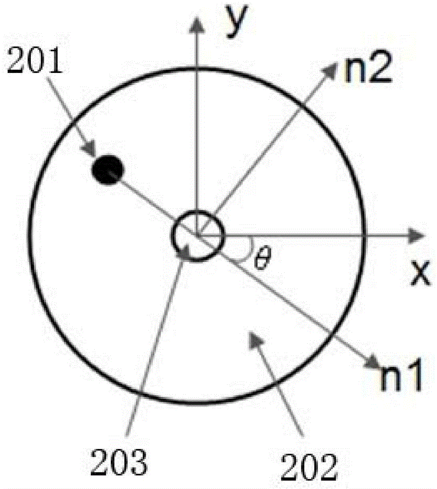
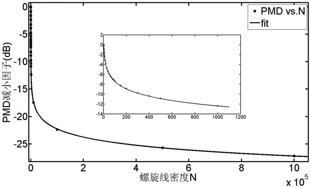
[0022] figure 1 The flow of the method for reducing optical fiber polarization mode dispersion provided by the embodiment of the present invention is shown, and only the parts related to the embodiment of the present invention are shown for convenience of description.

[0023] The method for reducing optical fiber polarization mode dispersion provided by this embodiment includes the following steps:

[0024] Step S101 , controlling the ultrafast optical signal to focus...


PUM


Abstract

The invention is applicable to the field of optical fiber production and manufacturing, and provides a method and a controller for reducing optical fiber polarization mode dispersion. The method introduces asymmetry on the cross-section of the optical fiber by controlling the interaction between the optical signal and the optical fiber to generate birefringence and reduce the polarization of the optical fiber. Mode dispersion, the method includes: controlling the ultrafast optical signal to focus inside the optical fiber to form a spot; controlling the spot and / or the optical fiber so that the spot moves relatively at a certain speed on the cross-section of the optical fiber, and at the same time controls the movement of the optical fiber along the length direction. The technology of the invention can break through the limitation of the optical fiber rotation speed in the prior art, so that the PMD of the optical fiber can be reduced by more than two orders of magnitude on the prior art level, and the requirement of high-speed and long-distance transmission can be met.

Description

technical field [0001] The invention belongs to the field of optical fiber production and manufacturing, and in particular relates to a method and a controller for reducing optical fiber polarization mode dispersion. Background technique [0002] An optical signal transmitted in an optical fiber has two polarization modes. For fibers with excellent circular symmetry in terms of geometry, internal stress, external stress, etc., operation at wavelengths or wavelength ranges considered "single-mode" actually supports two orthogonal polarization modes , where the two polarization modes are degenerate and travel at the same group velocity with no time delay after traveling the same distance in the fiber. [0003] In practice, however, optical fibers are not perfectly circularly symmetric. For example, imperfections such as geometric deformation and stress asymmetry destroy the degeneracy of the two modes. As a result, the two polarization modes are transmitted with different t...

Claims


Application Information

Patent Timeline
Patent Type & Authority Patents(China)
IPC IPC(8): G02B6/02
Inventor 曹祥东罗文清
Owner 青岛自贸激光科技有限公司
Learn More