Layered tool holder with visible identification

a tool holder and visible identification technology, applied in the field of tool holders, can solve the problems of foreign object debris or foreign object damage (fod), which is not compatible with large volume commercially available tool boxes, and achieves the effect of reducing or eliminating foreign object debris or foreign object damage (fod) and low cos

Inactive Publication Date: 2008-08-12
ADVANCED MATERIALS GROUP
View PDF9 Cites 57 Cited by
  • Summary
  • Abstract
  • Description
  • Claims
  • Application Information

AI Technical Summary

Benefits of technology

[0006]In accordance with teachings of the present invention, a tool holder and method of forming a tool holder are provided to overcome many of the shortcomings and disadvantages associated with prior tool holders. One aspect of the present invention includes providing a tool holder which may be fabricated at relatively low cost from two or more layers of material. Tool holders formed in accordance with teachings of the present invention may be used to substantially reduce or eliminate foreign object debris or foreign object damage (FOD) after repair and maintenance of complex equipment such as jet engines and large water pumps. Such tool holders may be used in a wide variety of industries from aircraft maintenance to nuclear reactor repair to complex surgical procedures to ensure that all tools and other objects have been accounted for after completion of an associated procedure.

Problems solved by technology

Many industries call for the use of unique tools which are not compatible with large volume commercially available tool boxes and tool drawers.
Foreign object debris or foreign object damage (FOD) is a well known problem associated with operation of jet engines and similar types of equipment.

Method used


Image

  • Layered tool holder with visible identification
  • Layered tool holder with visible identification
  • Layered tool holder with visible identification

Examples


Embodiment Construction

[0014]Preferred embodiments of the invention and its advantages are best understood by reference to FIGS. 1-6 wherein like numbers refer to same and like parts.

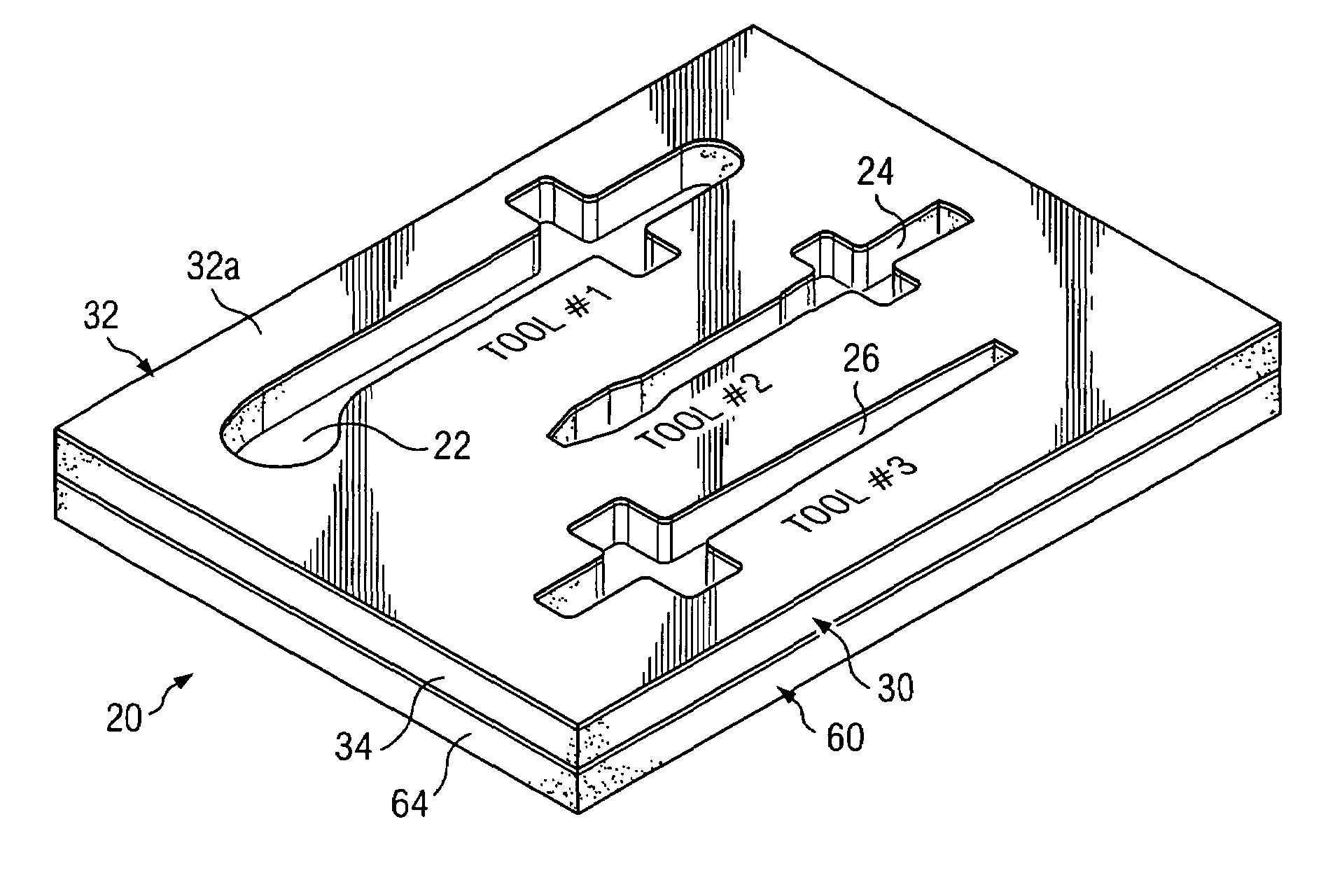
[0015]The term “tool holder” may be used in this application to describe any type of component or assembly formed in accordance with teachings of the present invention satisfactory for holding tools, tooling, devices or any other objects.

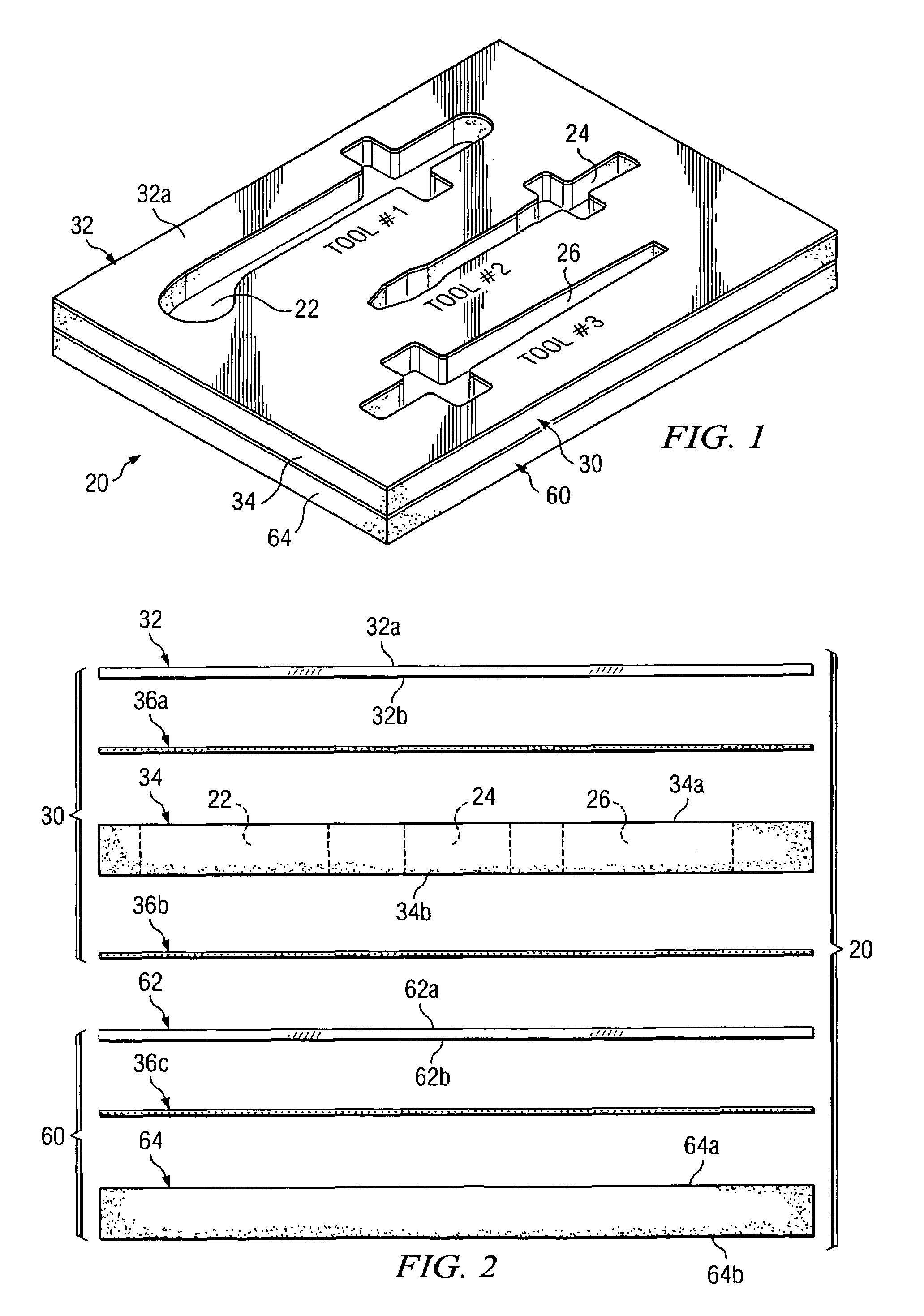
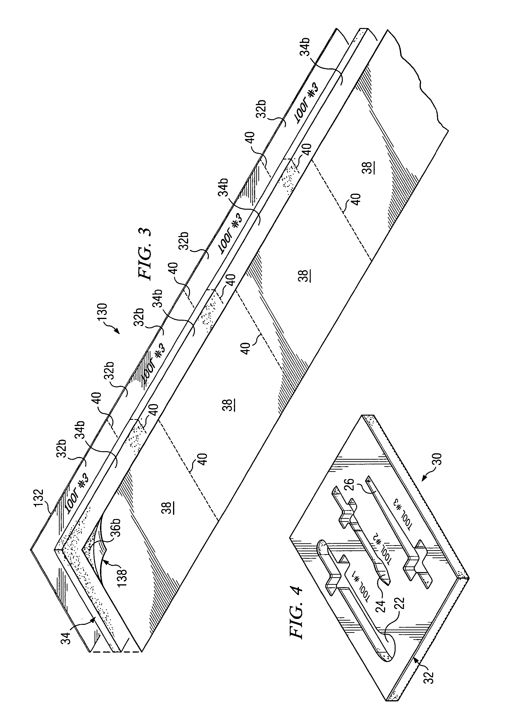
[0016]Tool holder 20 may be formed from multiple layers of material in accordance with teachings of the present invention. Tool holder 20 and associated layers of material may be formed in accordance with teachings of the present invention having various configurations including square, rectangular, triangular, circular, oval or any other satisfactory configuration. Multiple cutouts or pockets may be formed in tool holder 20 to receive respective tools or other devices. For example, cutouts 22, 24 and 26 as shown in FIG. 1 may be formed in tool holder 20 to receive respective tools (not expre...


PUM


Abstract

A tool holder formed from two or more layers of material is provided. Cutouts or pockets may be formed in the tool holder corresponding with specific types and sizes of tools. An identification for each tool may be provided on the tool holder adjacent to each cutout. The identification remains visible to a reader when an associated tool is placed in each respective cutout.

Description

RELATED APPLICATION[0001]This application claims priority to U.S. Provisional Patent Application Ser. No. 60 / 623,924, filed Nov. 1, 2004 and entitled “TOOL HOLDER,” the contents of which are hereby incorporated in their entirety by reference.TECHNICAL FIELD[0002]The present invention is related to tool holders having cutouts or pockets shaped to receive a specific size and type of tool and more particularly to tool holders formed from two or more layers of material.BACKGROUND OF THE INVENTION[0003]Tool boxes and tool chests frequently hold a wide variety of tools and other devices. Tool boxes and tool chests may include one or more drawers for specific types of tools. Such tool boxes and tool chests may include molded plastic inserts sized to receive specific sizes and types of tools. The type and / or size of the tool contained within each drawer may be printed on the exterior of the drawer. Also, the type and / or size of each tool may be printed on the molded plastic insert contained...

Claims


Application Information

Patent Timeline
Patent Type & Authority Patents(United States)
IPC IPC(8): B65D85/20
CPCB25H3/06
Inventor BOWEN, MICHAEL LDELK, ROBERT E
Owner ADVANCED MATERIALS GROUP
Why Eureka
Try Eureka