Walker device

a technology of walker and rollator, which is applied in the direction of hand carts, conveyors, transportation and packaging, etc., can solve the problems of affecting the use of users' mobility, the length of the brake wire often constitutes an obstruction, etc., and achieves reliable transmission of force, eliminates any risks of user injuries, and facilitates the vertical adjustment of the rollator

Inactive Publication Date: 2008-08-12
CARRERA OPTYL MARKETING +1
View PDF5 Cites 37 Cited by
  • Summary
  • Abstract
  • Description
  • Claims
  • Application Information

AI Technical Summary

Benefits of technology

[0007]A further object of the invention is that it should be simple and safe. Yet another object of the invention is that it should use few components that could be manufactured at low costs and could be mounted in a smooth and easy manner.
[0018]In accordance with one particular embodiment, the coupling means may be configured in such a manner that its very shape causes it to be locked to the lower force transmission member when the brake-control means leaves its neutral position. By such shape-induced locking should primarily be understood force transmission between the coupling means and the lower force transmission member caused by shape. This shape-induced locking feature provides reliable transmission of force between the upper and lower force transmission members.

Problems solved by technology

In rollators of this kind, one consequence of the height-adjustability feature is that the length of the brake wire often constitutes an obstruction to the user.

Method used


Image

  • Walker device
  • Walker device
  • Walker device

Examples


Embodiment Construction

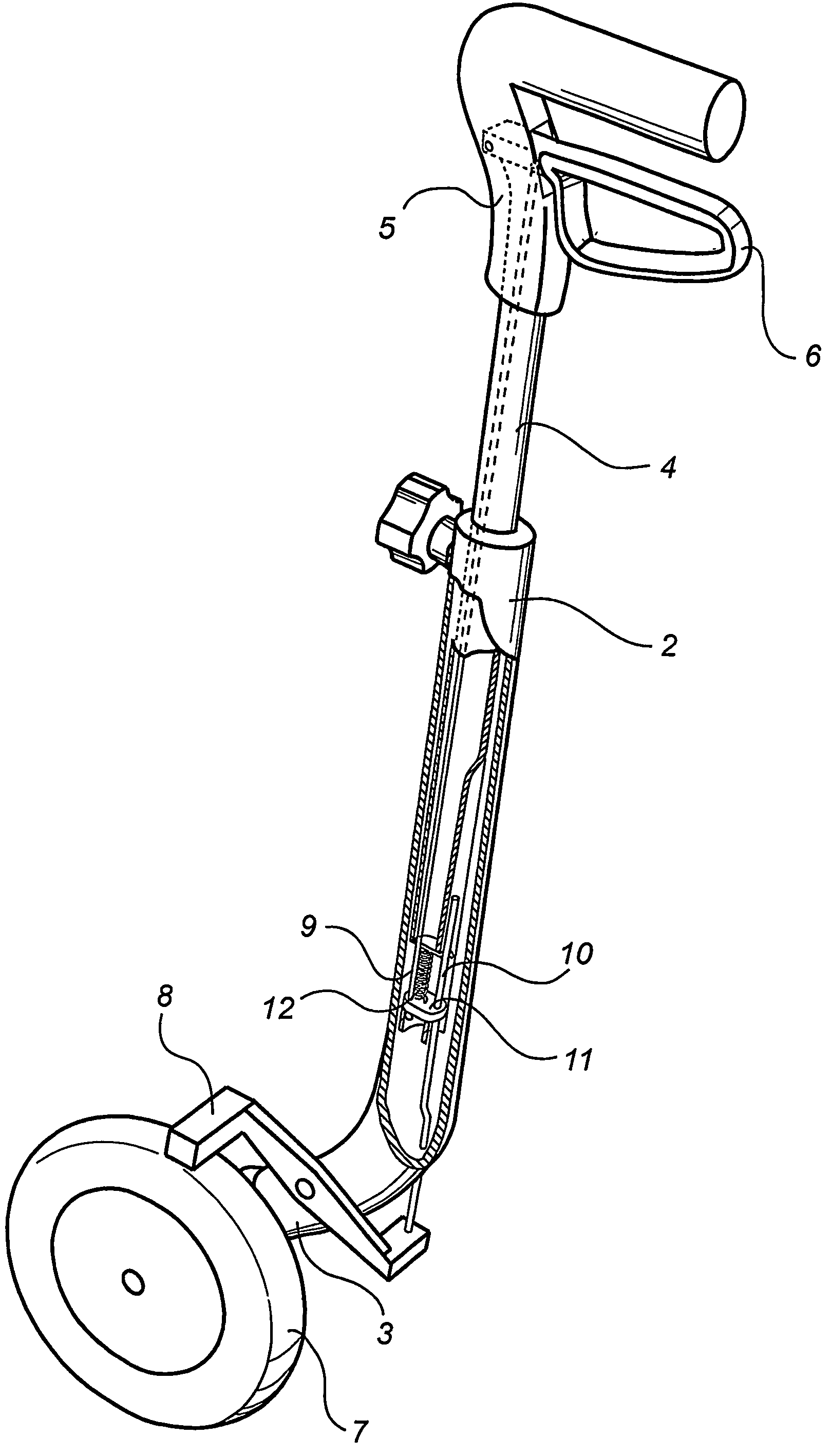
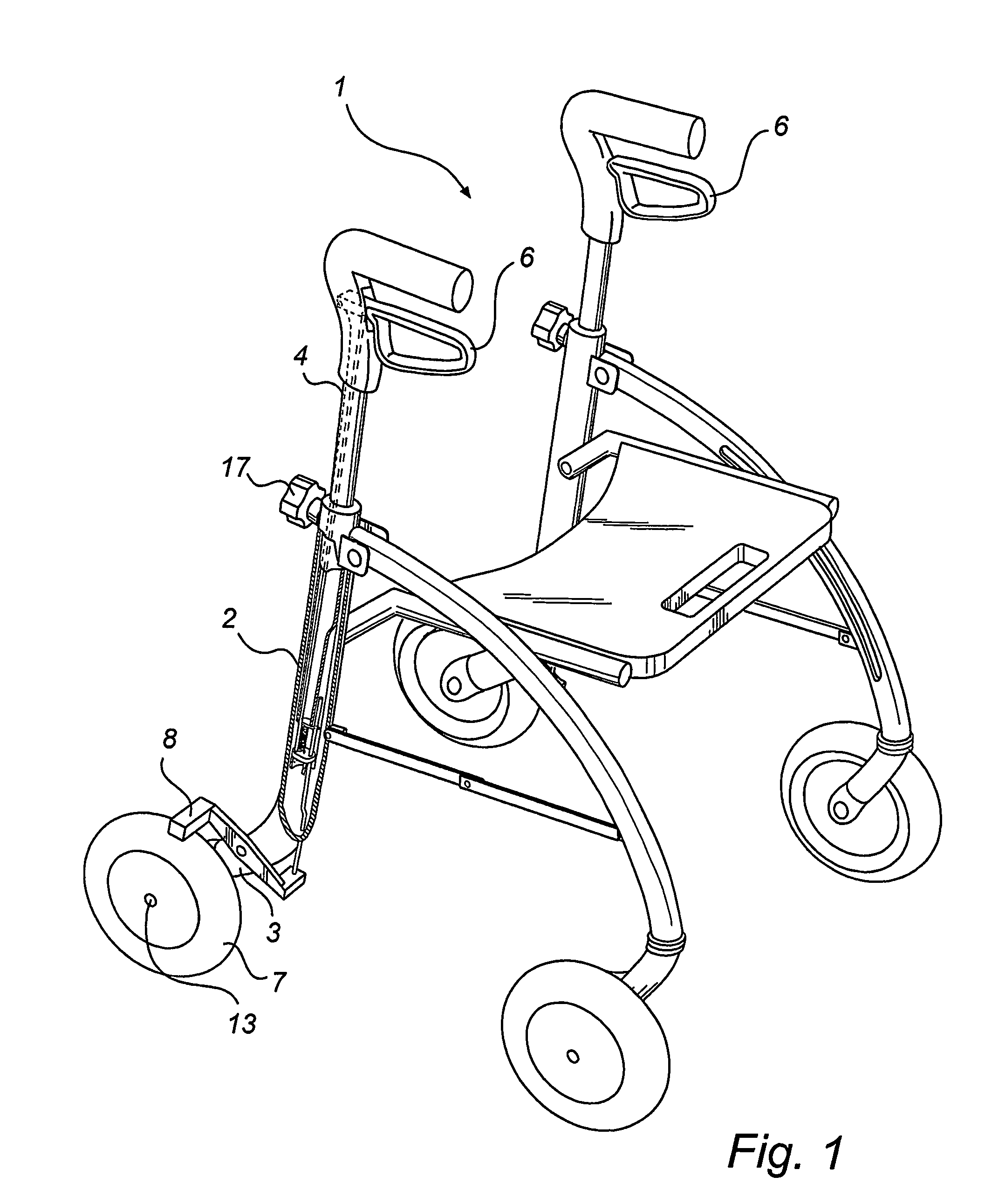
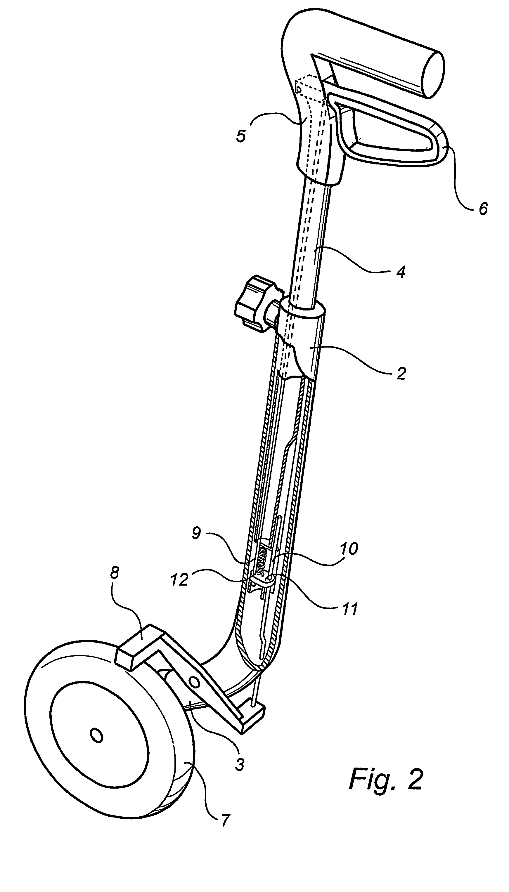
[0027]FIG. 1 shows a rollator 1 in accordance with one embodiment of the invention, which rollator comprises a frame member 2. The lower end 3 of the frame member supports a wheel 7, which is rotatably mounted on a wheel axle 13 in the frame. The lower end 3 of the frame member 2 also supports a brake element 8, which is mounted adjacent the wheel 7 at a predetermined radial distance from the latter.

[0028]The upper end of the frame member 2 is provided with an adjustable handle support rod 4. Preferably, the frame member 2 is adapted to receive the handle support rod 4 such that the latter may be fitted into a part of the frame member 2. Suitably, the respective interconnection parts of these components have essentially similar complementary cross-sectional shapes, such as circular, oval or polygonal. In accordance with the embodiment shown in FIG. 1, the lower end of the handle support rod 4 is slightly narrower than the rest of the rod over part of its extension. This narrower par...


PUM


Abstract

The invention concerns a device in wheeled walker or rollator, comprising a frame member (2) having a lower end (3), a handle support rod (4) having an upper end (5), a brake-control means (6) arranged at the upper end (5) of the handle support rod, said brake-control means (6) being movable between a neutral position and a brake-application position. The rollator comprises a wheel (7) located at the lower end (3) of the frame member, the distance between said wheel (7) and the brake-control means (6) being changeable, a brake element (8) located adjacent the wheel (7), an upper force-transmission member (9) connected to said brake-control means (6), a lower force-transmission member (10) connected to said brake element (8), and a coupling means (11) for coupling-together said upper and said lower force-transmission members (9, 10). The upper force-transmission member (9) and the lower force-transmission member (10) are arranged to move freely relative to one another, when the brake-control means (6) assumes its neutral position and. The upper force-transmission member (9) and the lower force-transmission member (10) are arranged to be interconnected by means of said coupling means (11), when the brake-control means (6) leaves the neutral position, in response to which braking force is transferred to the brake element (8).

Description

TECHNICAL FIELD OF INVENTION[0001]The present invention relates to a walker device or rollator, comprising at least one frame member having a lower end, at least one handle support rod having an upper end, a brake-control means arranged essentially at the upper end of the handle support rod, said brake-control means being movable between a neutral position and a brake-application position, a wheel located essentially at the lower end of the frame member, the distance between said wheel and the brake-control means being changeable, a brake element located adjacent the wheel, an upper force-transmission member connected to said brake-control means, a lower force-transmission member connected with said brake element, and a coupling means for coupling-together said upper and said lower force-transmission members.TECHNICAL BACKGROUND[0002]Walking devices or rollators of the kind outlined above are well known. Rollators of this kind are wheeled devices on which motor-handicapped individua...

Claims


Application Information

Patent Timeline
Patent Type & Authority Patents(United States)
IPC IPC(8): B62B3/02A61H3/04B60T11/04B65G17/38B62B5/04B65G17/08B65G17/40
CPCA61H3/04B62B5/04B60T11/04A61H2003/046B62B2206/06B62B5/0447B62B5/0485
Inventor LONKVIST, TORBJORN
Owner CARRERA OPTYL MARKETING
Why Eureka
Try Eureka