Paperboard container with bottom support
a bottom support and paperboard technology, applied in the field of packaging, can solve the problems of limiting the interior space of the container, requiring excessive amounts of additional material, and lessening the strength of the reinforcement system, and achieve the effect of preventing the sagging of the container bottom
- Summary
- Abstract
- Description
- Claims
- Application Information
AI Technical Summary
Benefits of technology
Problems solved by technology
Method used
Image
Examples
second embodiment
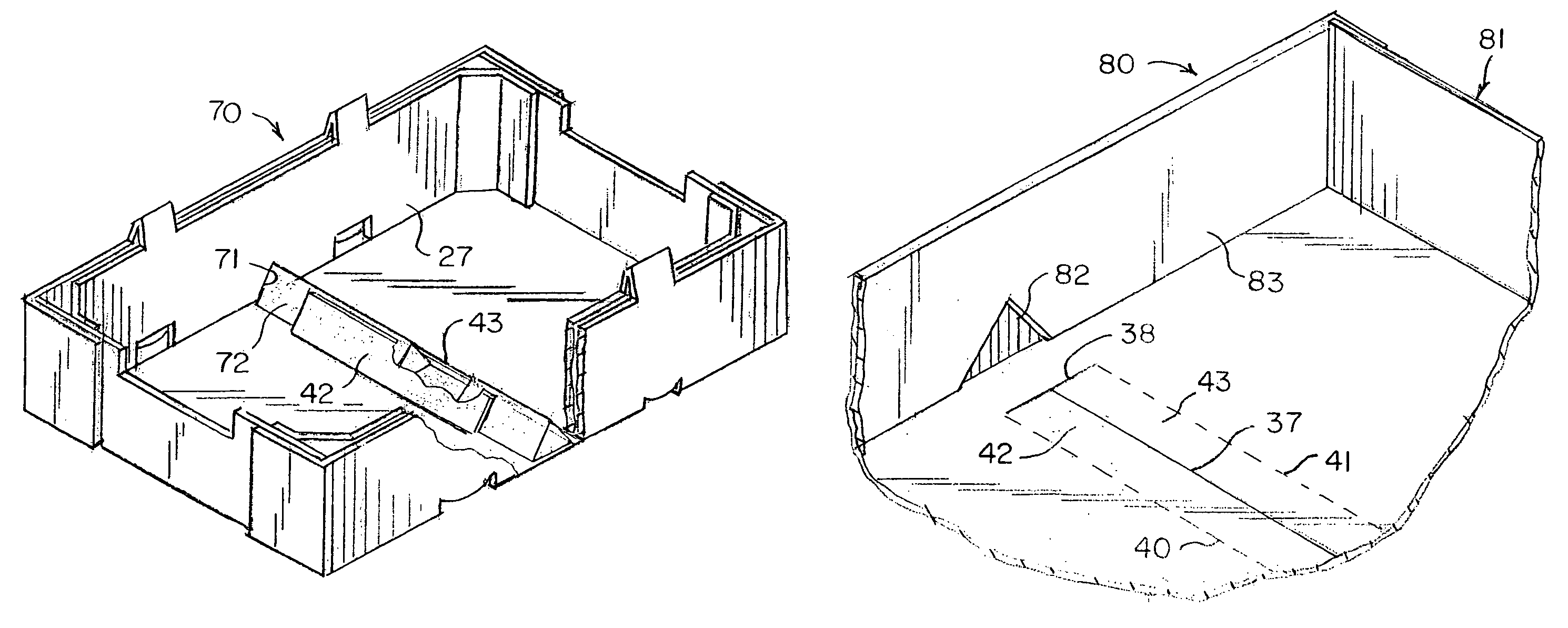
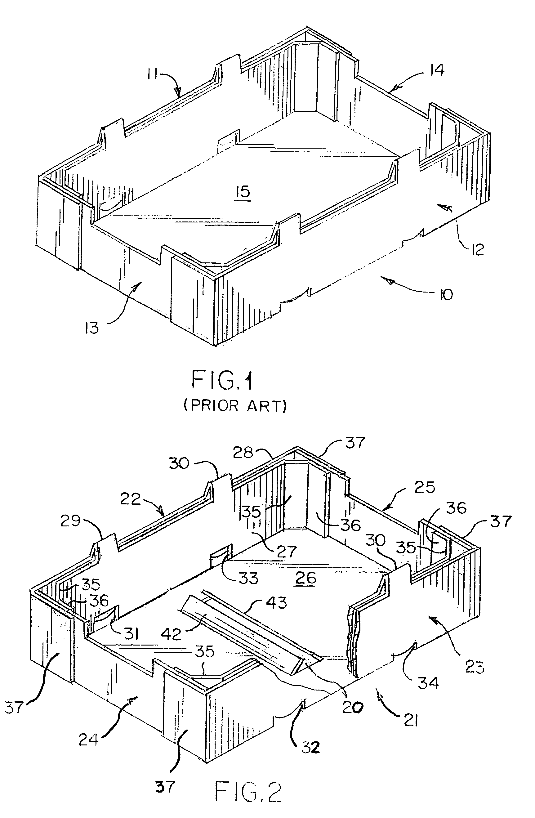
[0038]A second embodiment is shown at 70 in FIG. 7. This embodiment is similar to the embodiment of FIG. 2, except cut-outs 71 shaped complementally to the cross-sectional shape of the beam are made in the opposite inner side wall panels 27, forming recesses into which the opposite ends of an elongated beam 72 are inserted. Thus, in this form of the invention the beam is located and held in place both by the engagement of its opposite ends in the recesses, and by the adhesive attachment of the flaps to the top surfaces of the beam.
third embodiment
[0039]A third embodiment is shown at 80 in FIG. 8. In this embodiment, the container 81 is of simplified construction similar to the container shown in FIG. 1, but has the cuts 37, 38, and 39 (only some of which are shown) and scores 40 and 41, forming flaps 42 and 43 for adhesively attaching a cross beam (not shown) similarly to the FIG. 2 embodiment. In addition, crushed areas 82 are made in the inner facing surfaces of the opposite side walls 83, forming recesses into which the opposite ends of the beam (not shown) are inserted.
fourth embodiment
[0040]A fourth embodiment is shown at 90 in FIGS. 9 and 10. In this embodiment, the container is similar to the container of FIG. 2, but cross beam 91 is generally rectangular in transverse cross-sectional shape, with a flat top surface 92 extending generally parallel to the plane of the bottom wall 26. Cut-outs 93 shaped complementally to the cross-sectional shape of the beam are made in the opposite inner side wall panels 27 for receiving the ends of the cross beam, and modified flaps 94 and 95 are formed in the bottom wall for adhesive attachment to the beam. The flaps are defined by elongate transverse cut 37 and arched cuts 96 and 97 extending generally perpendicularly to each of the opposite ends of the cut 37, and longitudinally extending scores 98 and 99 extending between the outer ends of the arched cuts at opposite ends of the cut 37. It should be noted that the cuts do not necessarily have to be arched, such as for example they may be straight. Additional scores 100 and 1...
PUM
 Abstract
Description
Claims
Application Information
 - R&D
- Intellectual Property
- Life Sciences
- Materials
- Tech Scout
- Unparalleled Data Quality
- Higher Quality Content
- 60% Fewer Hallucinations
Browse by: Latest US Patents, China's latest patents, Technical Efficacy Thesaurus, Application Domain, Technology Topic, Popular Technical Reports.
© 2025 PatSnap. All rights reserved.Legal|Privacy policy|Modern Slavery Act Transparency Statement|Sitemap|About US| Contact US: help@patsnap.com


