Low-profile planar transformer

a planar transformer and low-profile technology, applied in the direction of transformer/inductance details, basic electric elements, coils, etc., can solve the problems of large clearance distance between core and windings, and the typical type of planar transformer is still relatively bulky, and achieves the effect of low profil

Inactive Publication Date: 2008-08-19
KUAN TECH (SHENZHEN) CO LTD
View PDF3 Cites 24 Cited by
  • Summary
  • Abstract
  • Description
  • Claims
  • Application Information

AI Technical Summary

Benefits of technology

[0008]It is therefore one object of the invention to provide a small planar transformer having a lower profile so that insulative clearance and creepage distances required between the primary winding and the secondary winding can be increased to an optimum.

Problems solved by technology

However, typical types of planar transformer have a drawback of having a great clearance distance between core and windings due to safety creepage consideration.
Thus, typical planar transformers are still relatively bulky as viewed by the inventor.

Method used


Image

  • Low-profile planar transformer
  • Low-profile planar transformer
  • Low-profile planar transformer

Examples


Embodiment Construction

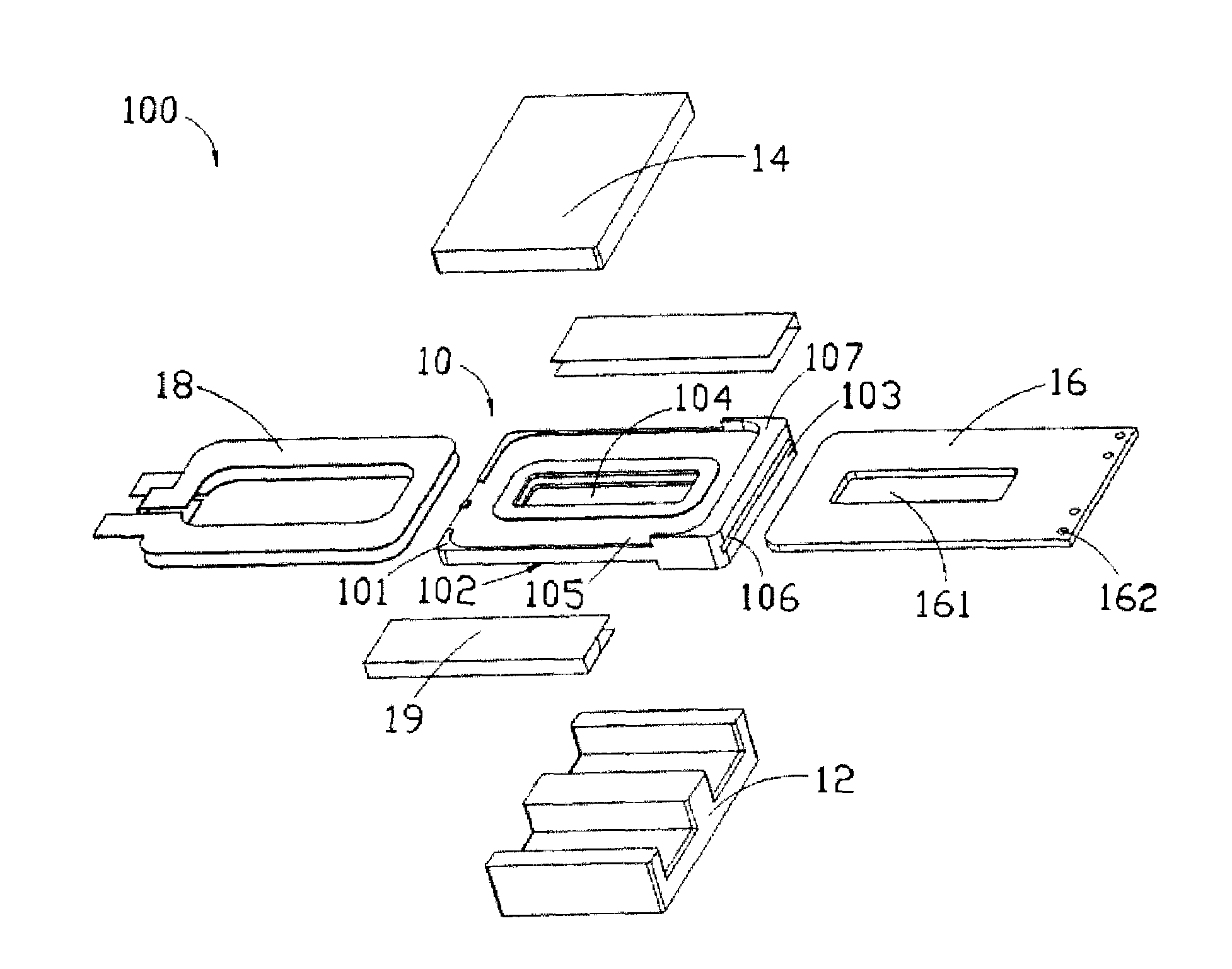
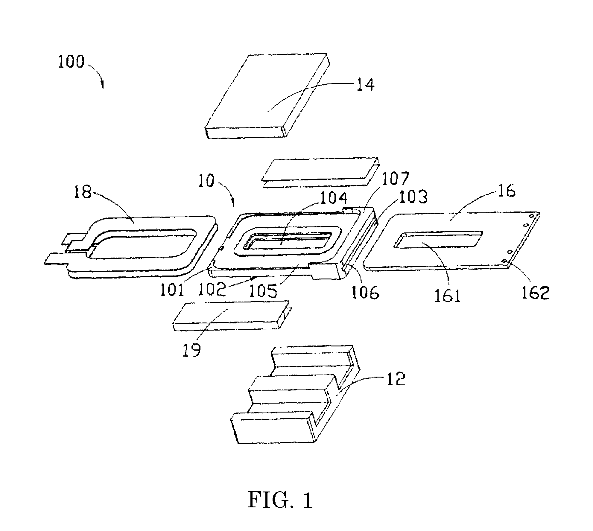
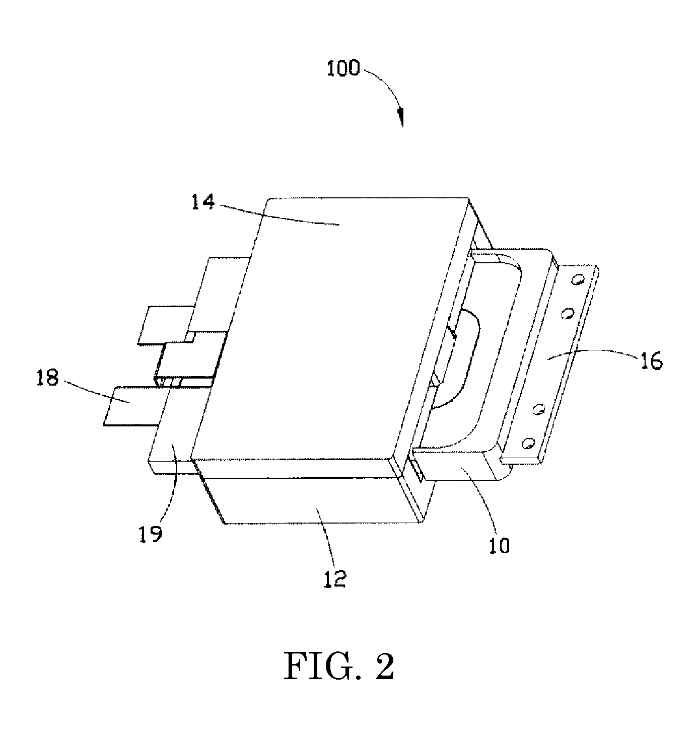
[0013]Referring to FIGS. 1 to 3, a planar transformer 100 in accordance with a preferred embodiment of the invention is shown. The transformer 100 comprises the following components as discussed in detail below.

[0014]A frame 10 is mounted between a first core 12 and a second core 14. The frame 10 comprises a hollow, rectangular body (not numbered) having a top surface 101, a bottom surface 102, two sides 103, a central, rectangular opening 104 through the top and bottom surfaces 101 and 102, two recessed structures 105 on the top and bottom surfaces 101 and 102 respectively, and a transverse slot 106 having a blind end proximate one side 103 and the other end open to the other side 103, the slot 106 being in communication with the opening 104.

[0015]A primary winding 16 is shaped as a rectangular sheet. The primary winding 16 is implemented as a printed circuit board (PCB). The primary winding 16 comprises a central, rectangular opening 161 through its top and bottom surfaces, and a ...


PUM

PropertyMeasurementUnit
shapeaaaaaaaaaa
ferromagneticaaaaaaaaaa
sizeaaaaaaaaaa

Abstract

A low-profile planar transformer in one embodiment includes a rectangular frame including top and bottom recesses, a first opening through the top and the bottom, a transverse slot open to the other side, and a flange on the other side; a sheet primary winding including a second opening through its top and bottom, the primary winding being adapted to insert into the slot with the other side thereof exposed and the second opening aligned with the first opening; a rectangular secondary winding adapted to put on the recesses; two insulators of U-shaped adapted to clamp front and rear ends of the secondary winding; a first core of E shape; and a second core of sheet shape adapted to couple to the first core by inserting the central ridge of the first core through the first and the second openings with the frame, the windings, and the insulators disposed therebetween.

Description

BACKGROUND OF THE INVENTION[0001]1. Field of Invention[0002]The invention relates to planar transformers and more particularly to a small planar transformer having a lower profile than conventional planar transformer.[0003]2. Description of Related Art[0004]Planar transformers are well known in the art. Planar transformers have advantages of having a compact size, a high efficiency, and a good heat dissipation capability.[0005]Moreover, there have been numerous suggestions in prior patents for planar transformers. For example, U.S. Pat. No. 5,010,314 discloses a type of low-profile planar transformer.[0006]Typically, a small planar transformer is mounted in a compact electronic product (e.g., notebook computer, MP3 player, or the like) for supplying required power thereto. However, typical types of planar transformer have a drawback of having a great clearance distance between core and windings due to safety creepage consideration. Thus, typical planar transformers are still relativ...

Claims


Application Information

Patent Timeline
Patent Type & Authority Patents(United States)
IPC IPC(8): H01F5/00
CPCH01F27/2804H01F27/324H01F2027/2819
Inventor CHENG, CHUN-GHENG
Owner KUAN TECH (SHENZHEN) CO LTD
Why Eureka
Try Eureka