Computer for dynamically determining interrupt delay

a computer and delay technology, applied in the field of interrupt control system, can solve the problems of constant delay in the response from the occurrence of an interrupt event, increase in the processing load of a processor, and reduce the performance of the system

Inactive Publication Date: 2008-08-19
FUJITSU LTD
View PDF10 Cites 12 Cited by
  • Summary
  • Abstract
  • Description
  • Claims
  • Application Information

AI Technical Summary

Problems solved by technology

When interrupts frequently occur, and the interrupt intervals become shorter, the interrupt processing load of a processor increases, thereby possibly reducing the performance of the system.
There are three problems with the interrupt coalescing as the above-mentioned conventional technology.
The first problem is that the response from the occurrence of an interrupt event is constantly delayed because an interrupt is delayed on a constant condition from the occurrence of an interrupt event.
The second problem is that since the load status of a processor is not considered, an adaptive process cannot be performed by, for example, immediately performing an interrupt when the load of a processor is small, and delaying an interrupt when the load of the processor is large.
The third problem is that although an I / O device is used with a card, etc. inserted, and the optimum condition for the interrupt delay between the card and the processor depends on a card, etc., the conventional technology uses fixed delay conditions without adjustments.

Method used


Image

  • Computer for dynamically determining interrupt delay
  • Computer for dynamically determining interrupt delay
  • Computer for dynamically determining interrupt delay

Examples


first embodiment

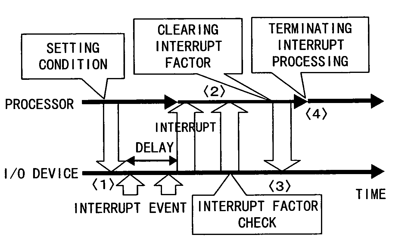
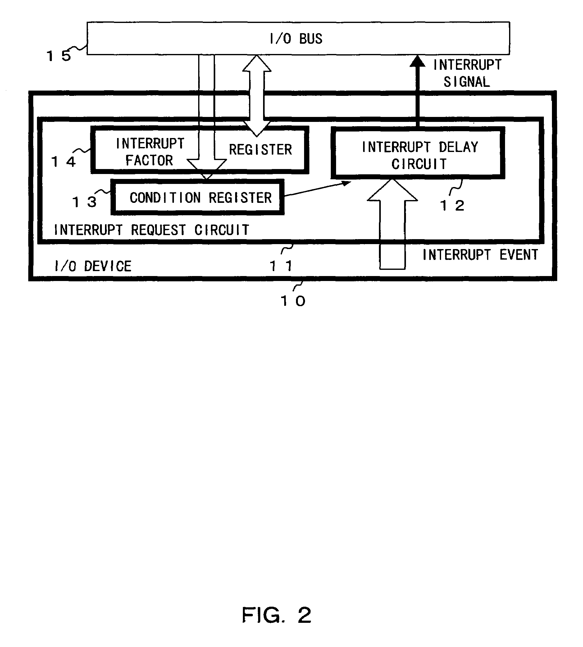
[0061]FIG. 2 is a block diagram showing the configuration of the interrupt request circuit according to the present invention. And FIG. 3 shows the flow of the interrupt processing shown in FIG. 2.

[0062]In FIG. 2, a condition register 13 stores the delay condition from the occurrence of an interrupt event to the issue of an interrupt (request) signal by an interrupt delay circuit 12 in an I / O device 10 to a processor through an I / O bus 15 as with the condition register 61 described by referring to the conventional technology shown in FIG. 21. The delay condition is dynamically determined by the processor depending on the load status of the processor, and the condition is stored in the condition register 13.

[0063]That is, the processor explicitly notifies an I / O device 11 of the interrupt delay condition, that is, the delay time from the occurrence of an interrupt event to the issue of an interrupt signal by the interrupt delay circuit 12, or the number of interrupt events occurring ...

second embodiment

[0072]In the second embodiment, the load status of a processor is estimated by measuring the time from the output of an interrupt signal for an interrupt event which has occurred at a point in time to the clear of the interrupt factor stored in the interrupt factor register 14, and the interrupt delay time for the interrupt event which next occurs is determined based on the estimated time.

[0073]In FIG. 7, the interrupt factor is stored in the interrupt factor register 14 when the interrupt signal is output immediately after an interrupt event occurs, and simultaneously the timer 21 is activated, and the time until the contents of the interrupt factor register 14 are cleared by the processor is measured. Then, the time is provided for a delay time determination circuit 20 for use in determining the interrupt delay time corresponding to the occurrence of the next interrupt event.

[0074]In determining the delay time, the measurement value of the timer 21 can be used as is, but the measu...


PUM


Abstract

In a computer having a unit for outputting an interrupt request to a processor, a delay condition from occurrence of an interrupt event to issue of an interrupt request to the processor can be dynamically determined depending on the processor load status, etc. The interrupt request output unit includes a unit for obtaining a determination factor of a delay condition from the occurrence of an interrupt event to the issue of an interrupt request to the processor, and a unit for determining a delay condition corresponding to the obtained determination factor. For example, a time up to a read of an interrupt factor by the processor is obtained as a determination factor, and is multiplied by a coefficient, thereby determining a delay time as a delay condition.

Description

CROSS REFERENCE TO RELATED APPLICATION[0001]This application is a continuing application, filed under 35 U.S.C. §111(a), of International Application PCT / JP02 / 00516, filed Jan. 24, 2002 incorporated by reference herein.BACKGROUND OF THE INVENTION[0002]1. Field of the Invention[0003]The present invention relates to an interrupt control system, and more specifically to a computer system capable of dynamically determining the delay time, for example, from an external input of an interrupt event to an output of an interrupt request of an interrupt request output unit in a computer system to a processor depending on the load status of the processor.[0004]2. Description of the Related Art[0005]When an interrupt event requiring external interrupt processing by a processor is input to a computer system, for example, an I / O device which receives the interrupt event issues an interrupt (request) signal to the processor, and the processor performs corresponding interrupt processing. For exampl...

Claims


Application Information

Patent Timeline
Patent Type & Authority Patents(United States)
IPC IPC(8): G06F13/24G06F3/00G06F9/46G06F9/48
CPCG06F13/24G06F9/4812
Inventor JINZAKI, AKIRA
Owner FUJITSU LTD
Why Eureka
Try Eureka