
Connector

a technology of connecting parts and connectors, applied in the direction of coupling contact members, coupling device connections, coupling/disassembly parts, etc., can solve the problem of increasing the force required for inserting the fpc into the receiving space of the housing, and achieve the effect of preventing the connected object from being easily removed from the connector

Inactive Publication Date: 2008-08-26
JAPAN AVIATION ELECTRONICS IND LTD
View PDF9 Cites 16 Cited by
  • Summary
  • Abstract
  • Description
  • Claims
  • Application Information

AI Technical Summary

Benefits of technology

[0010]With the arrangement of the connector according to the present invention, it is easy to insert the connected object into the receiving space, and after the connected object is inserted into the receiving space, a large contact force is generated between the contact portions of the contacts and the connected object.
[0012]With the arrangement of the preferred embodiment, it is possible to prevent the connected object from being easily removed from the connector.

Problems solved by technology

This has been a factor which causes an increase in the force required for inserting the FPC into the receiving space of the housing.

Method used


Image

  • Connector
  • Connector
  • Connector

Examples


Embodiment Construction

[0038]The present invention will now be described in detail with reference to the drawings showing preferred embodiments thereof.

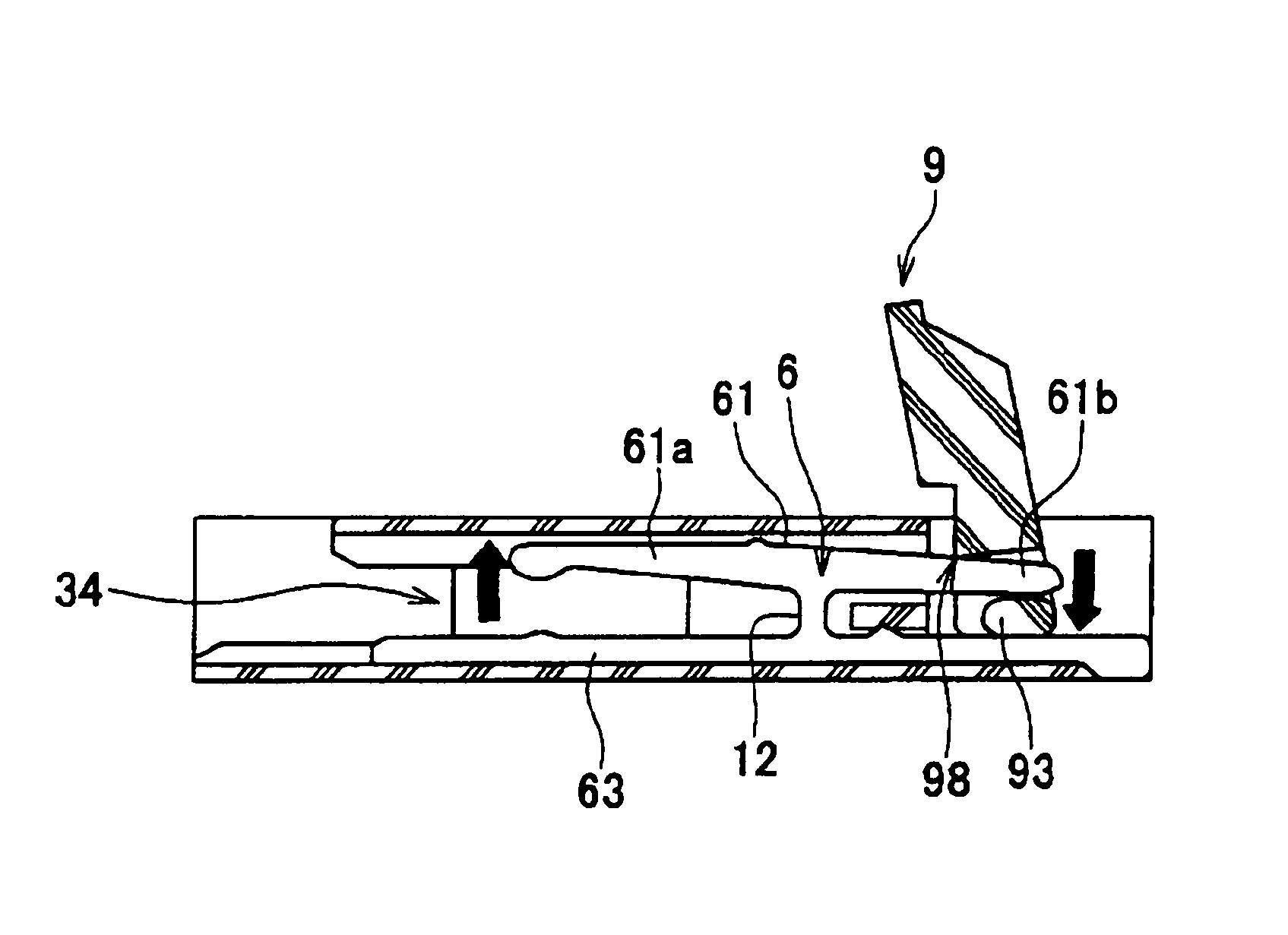
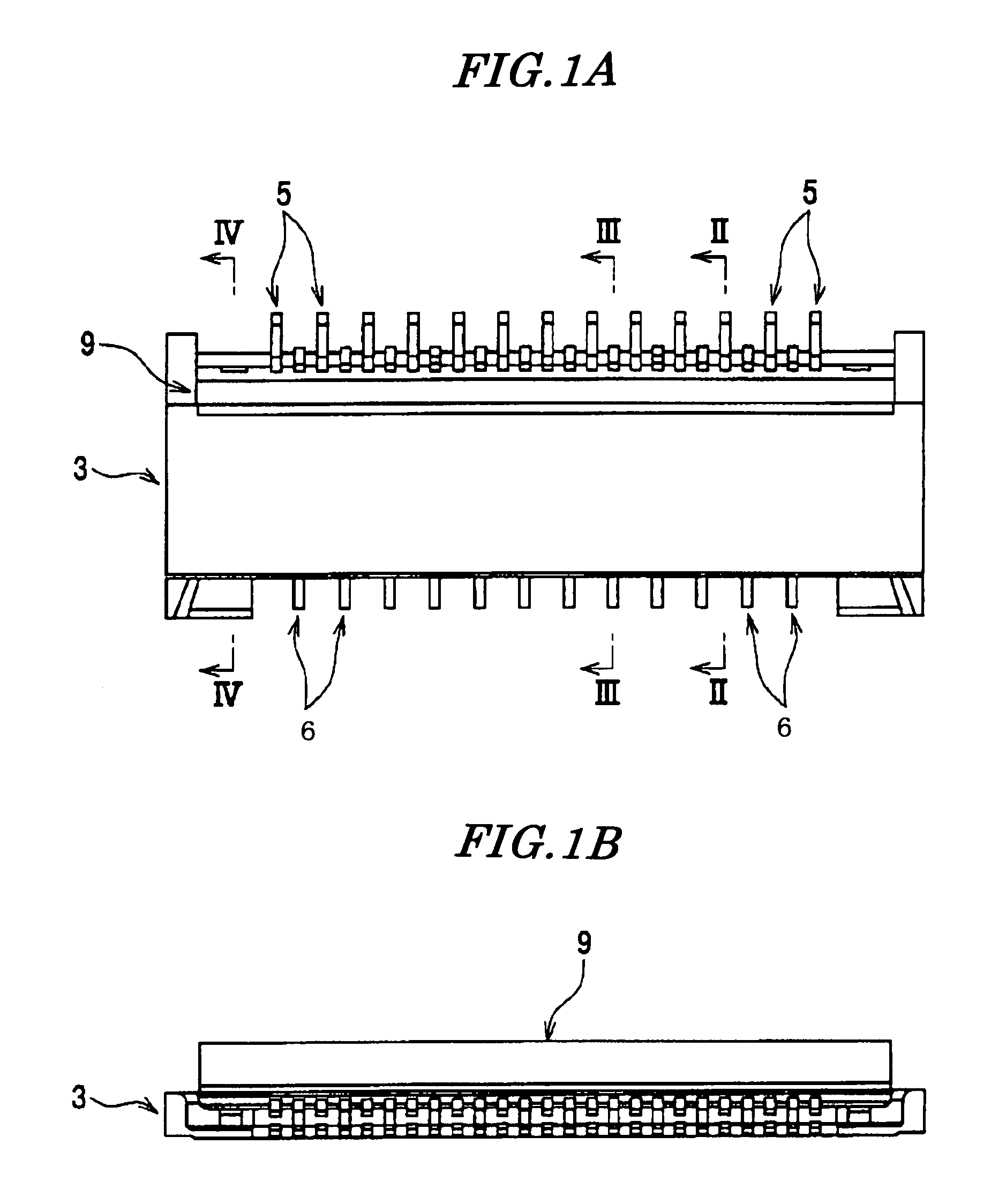
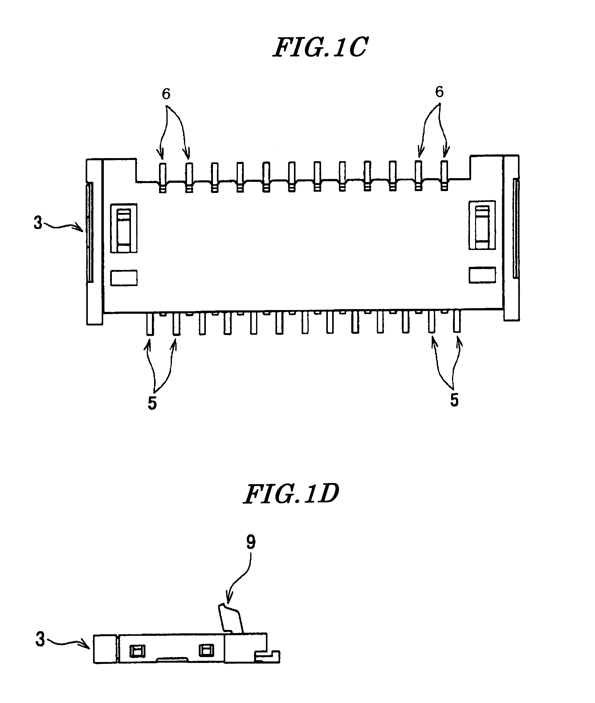
[0039]Referring to FIGS. 1 to 4, the connector is for an FPC (connected object), and is comprised of a housing 3, the first contacts 5, the second contacts 6, and the actuator 9.

[0040]As shown in FIGS. 2 and 3, the housing 3 includes a ceiling 31, a bottom 32, and a connecting portion 33. Formed between the ceiling 31 and the bottom 32 is an FPC-receiving space (receiving space) 34.

[0041]The ceiling 31 has accommodation grooves 31a and accommodation grooves 31b formed in a lower surface thereof such that they are arranged alternately in the longitudinal direction of the housing 3. An upper surface of the ceiling 31 is covered with a shield plate 11.

[0042]The bottom 32 has accommodation grooves 32a and accommodation grooves 32b formed in an upper surface thereof such that they are arranged alternately in the longitudinal direction of the housing 3.

[0043]The...


PUM


Abstract

A connector capable of facilitating the insertion of a connected object, and obtaining a sufficient contact force. Contacts are held by a housing including a receiving space into which is inserted FPC. An actuator is mounted in the housing in a manner pivotally movable between open position for inserting FPC into the space, and closed position for holding FPC therein. The contacts have respective seesaw-type beams having one ends thereof formed with portions for contact with FPC, and the other ends thereof formed with power point portions for receiving the turning force of the actuator. The actuator has pressing portions for pushing downward the power point portions when open, to thereby lift them to move the contact portions out of the space, and cam portions for pushing upward the same when closed, to thereby push them downward to cause the contact portions to enter the space.

Description

BACKGROUND OF THE INVENTION[0001]1. Field of the Invention[0002]This invention relates to a connector, and more particularly to a connector suitable for electrically connecting between an FPC (Flexible Printed Circuit) and a printed circuit board.[0003]2. Prior Art[0004]Conventionally, there has been proposed a connector comprising a plurality of contacts, a housing that holds the contacts, and an actuator that is rotatably mounted on the housing and elastically deforms the contacts to thereby bring the contacts into contact with an FPC (see Japanese Laid-Open Patent Publication (Kokai) No. 2004-221067).[0005]The contacts each include a seesaw-type beam that has one end thereof formed with a contact portion for contact with the FPC, and the other end thereof formed with a power point portion on which the turning force of the actuator acts.[0006]When the actuator is pivotally moved from an FPC-inserting position to an FPC-connecting position, the power point portions of the contacts ...

Claims


Application Information

Patent Timeline
Patent Type & Authority Patents(United States)
IPC IPC(8): H01R12/24H01R12/79
CPCH01R12/57H01R12/88H01R12/79H01R13/639H01R12/77H01R12/82
Inventor HASHIGUCHI, OSAMUINOUE, KANJI
Owner JAPAN AVIATION ELECTRONICS IND LTD
Learn More