
Self-supplied electronic protection device for automatic circuit-breakers

a self-supplied, electronic protection device technology, applied in the direction of emergency protection for supplying operative power, emergency protection for limiting excess voltage/current, circuit-breaking switches, etc., can solve the problems of virtually inability to provide protection, failure or fault of the circuit-breaker protection part, and enormous and irreversible damag

Active Publication Date: 2008-08-26
ABB SPA
View PDF4 Cites 3 Cited by
  • Summary
  • Abstract
  • Description
  • Claims
  • Application Information

AI Technical Summary

Benefits of technology

[0017]The subject of the present invention is a protection device of an innovative type equipped with a microcontroller that makes the protection function SCinst available in a very short time and exploiting all the potential of a microcontroller, without the use of additional protection devices.

Problems solved by technology

Amongst the possible failures there exist, in particular, initial instantaneous short circuits, characterized by currents Iinst, which can cause enormous and irreversible damage even in periods of time in the region of a few milliseconds.
A circuit-breaker that does not envisage any additional strategy, during the time Tsu is consequently virtually unable to provide any protection.
Hence, any failure or fault that may occur in the part of the system protected by the circuit-breaker during this time Tsu cannot be adequately interpreted by the relay.
At the current state of the art, just the reduction of Tsu is therefore insufficient to set a circuit-breaker in conditions of safety in the case of instantaneous short circuits.
They are normally calibrated in a fixed way so that they trip at current levels that are certainly dangerous, namely when the lack of interruption of the main circuit in times shorter than the time Tsu defined above is likely to expose the stretch of electrical network protected by the circuit-breaker or the circuit-breaker itself to permanent damage.

Method used


Image

  • Self-supplied electronic protection device for automatic circuit-breakers
  • Self-supplied electronic protection device for automatic circuit-breakers

Examples


Embodiment Construction

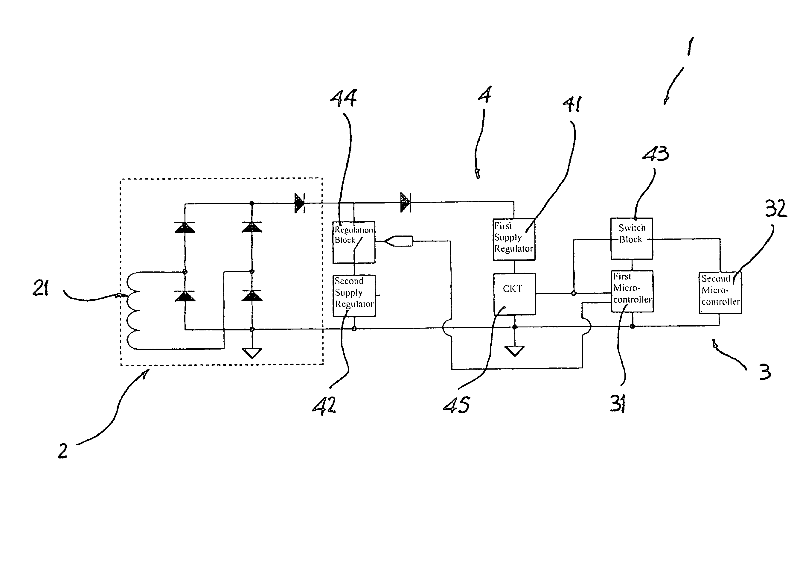
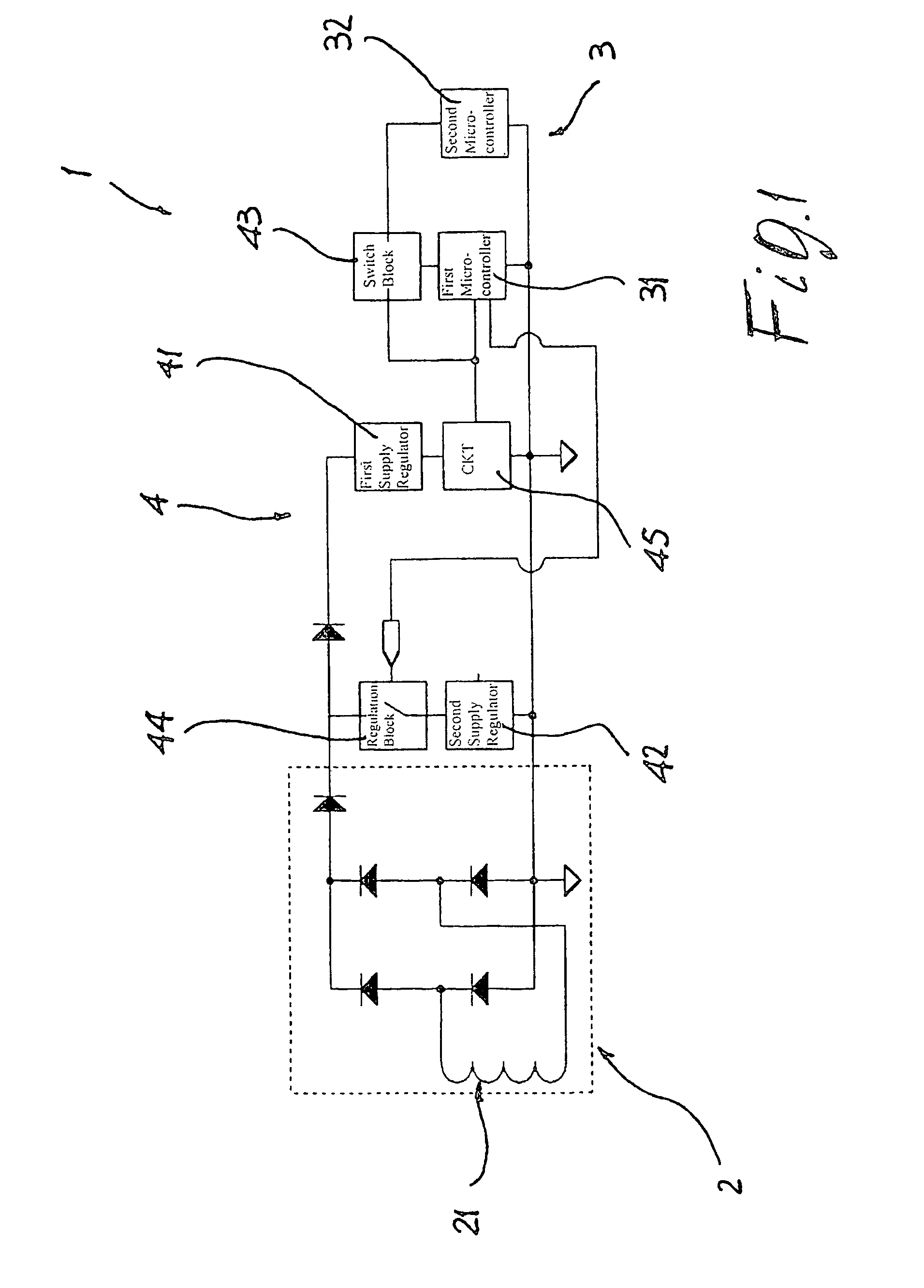
[0046]With reference to FIG. 1, the electronic self-supplied protection device according to the invention, designated as a whole by the reference number 1, comprises a supply device 2 that draws energy from the stretch of electrical network protected by the circuit-breaker to which the protection device itself is associated. Preferably, the supply device 2 comprises one or more current transformers 21 which draw energy from the conductors of the stretch of electrical network protected by said circuit-breaker.

[0047]The device according to the invention moreover includes a control device 3, which comprises at least two levels of operation, the first of said at least two levels of operation being associated to the function of protection from instantaneous short-circuit SCinst, the second and possible further levels of operation being associated to further functions of said protection device. There is moreover present a selective interface device 4, which comprises means for regulating ...


PUM


Abstract

An electronic self-supplied protection device for automatic circuit-breakers that includes: a supply device that draws energy from the stretch of electrical network protected by said circuit-breaker; a control device with at least two levels of operation, where the first of the at least two levels of operation being associated to the function of protection from instantaneous short-circuit SCinst. In addition, second and possible further levels of operation of the self-supplied protection device are associated with further functions of said protection device; a selective interface device including means for regulating the supply, which, in a first step, immediately following upon closing of the circuit by the circuit-breaker, supply the first level of operation, and, after a controlled period of time, supply also the second and possible further levels of operation of said control device.

Description

FIELD OF THE INVENTION[0001]The present invention relates to electronic protection devices provided with a self-supply system and equipped with a microcontroller (said protection devices being referred to briefly hereinafter as relays), for automatic circuit-breakers (hereinafter referred to briefly as circuit-breakers).[0002]By “self-supplied relays” are meant relays capable of functioning also without a specific auxiliary supply, using that is, for their operation, energy drawn, via a supply device, directly from the stretch of electrical network protected by the circuit-breaker. The supply device of the relay is typically constituted by one or more current transformers that draw energy from the stretch of electrical network protected by the circuit-breaker, and by electronic circuits, which supply an adequate electrical supply to the relay.BACKGROUND OF THE INVENTION[0003]As is known from the prior art, amongst the various functions performed by a relay, the main one is that of d...

Claims


Application Information

Patent Timeline
Patent Type & Authority Patents(United States)
IPC IPC(8): H02H3/08H02H1/06H02H3/05H02H3/093
CPCH02H1/063H02H3/0935H02H3/05
Inventor VIARO, FRANCESCOSTUCCHI, MARCO
Owner ABB SPA
Learn More