Gas sensor and control method therefor

a technology of gas sensor and control method, which is applied in the field of gas sensor, can solve the problems of deterioration of, damage to, and easy condensation of off-gas moisture content, and achieve the effect of reducing the accuracy of detection, preventing damage to, and deteriorating of gas sensors

Inactive Publication Date: 2008-09-02
HONDA MOTOR CO LTD
View PDF21 Cites 8 Cited by
  • Summary
  • Abstract
  • Description
  • Claims
  • Application Information

AI Technical Summary

Benefits of technology

[0008]The present invention was made in view of the above circumstances and the object thereof is to prevent damage to, deterioration of, and reduction in accuracy of detection of a gas sensor.
[0010]According to the gas sensor, even when the relative humidity of the detection gas in the gas detection chamber is high, the relative humidity of the detection gas can be decreased by the dehumidifying element. In addition, even when condensation occurs in the gas detection chamber, any condensed water produced can be absorbed by the dehumidifying element. Accordingly, it becomes possible to prevent deterioration of the detecting element and the compensating element due to electricity supplied to the detecting element and the compensating element while the condensed water is adhered to surfaces of the detecting element and the compensating element.
[0012]In this case, heat generated by the heater decreases the relative humidity inside the gas detection chamber, and the water absorbed in the dehumidifying element is drained off. As a result, the amount of absorbable water in the dehumidifying element is increased. Furthermore, even when the relative humidity is increased due to a temperature drop inside the gas detection chamber when operation of the heater is stopped, water such as moisture contained in the detection gas in the gas detection chamber can be absorbed. As a result, it becomes possible to suppress condensation in the gas detection chamber.
[0019]In this case, the dehumidifying element can be maintained in a water-absorbable condition by setting the temperature of the dehumidifying element equal to the temperature in which water absorbed in the dehumidifying element is drained off from the dehumidifying element, and is condensed, etc., or to a predetermined temperature higher than the above-mentioned temperature. As a result, the occurrence of condensation in the gas detection chamber can be suppressed. Furthermore, the permeability of gas flowing into the gas detection chamber can be maintained.

Problems solved by technology

In this case, deterioration of, and damage to, the hydrogen detector may occur.
In particular, in the solid high-polymer membrane-type fuel cell, since the normal operating temperature is lower than the evaporation temperature of water, and since the off-gas is highly humid and gas having high water content is discharged, there is a problem in that the moisture content of the off-gas readily condenses.
Furthermore, for example, when the gas-contact combustion-type hydrogen detector is provided, particularly when provided in the exhaust system on the oxygen electrode side of the fuel cell, if electricity is supplied to the gas detecting element while humidifying water or reaction-generated water and the like is adhered to it, localized non-uniformities in temperature distribution may occur on the surface of the element, and may result in damage to, and decreased sensitivity of, the element.

Method used


Image

  • Gas sensor and control method therefor
  • Gas sensor and control method therefor
  • Gas sensor and control method therefor

Examples


Embodiment Construction

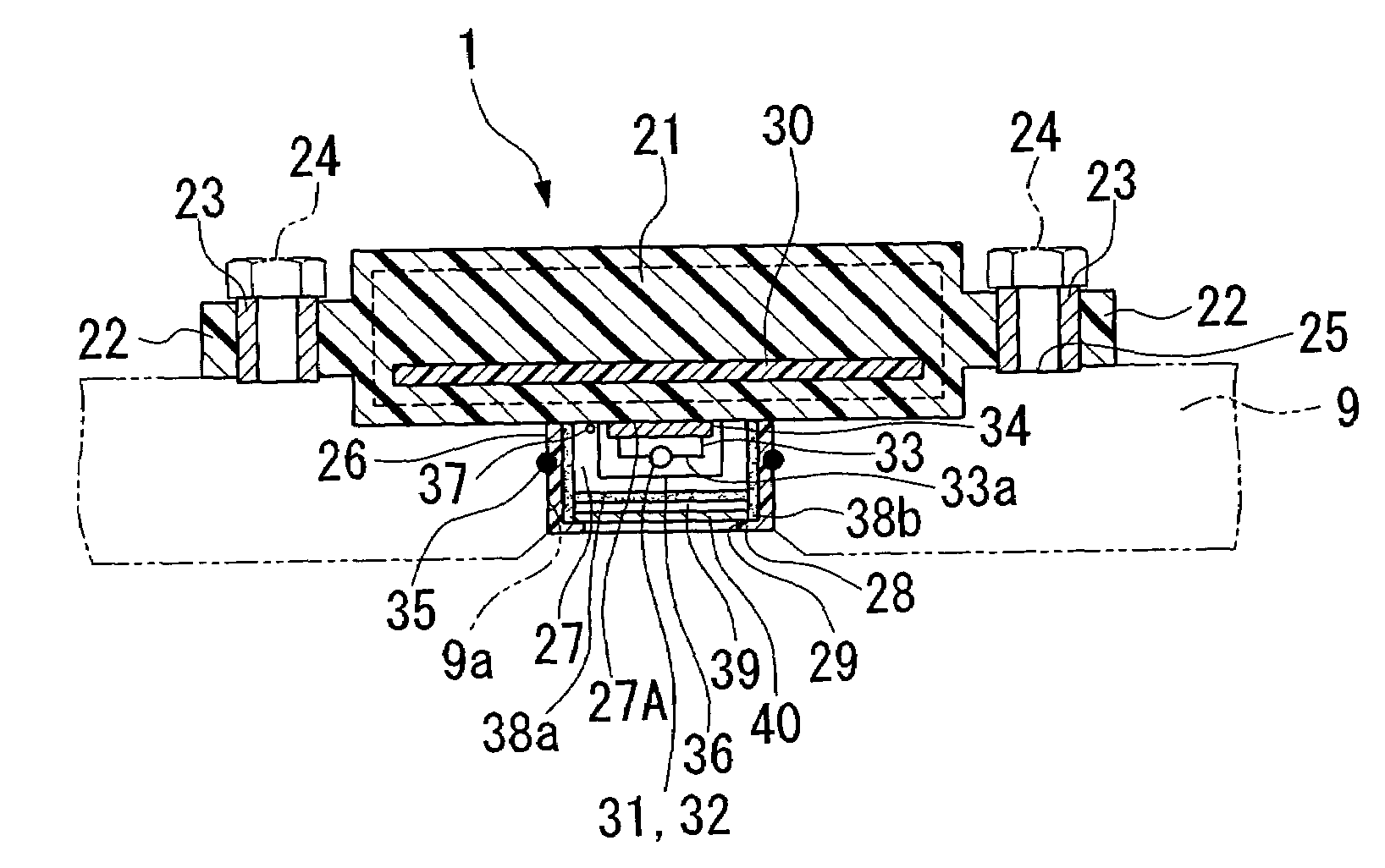
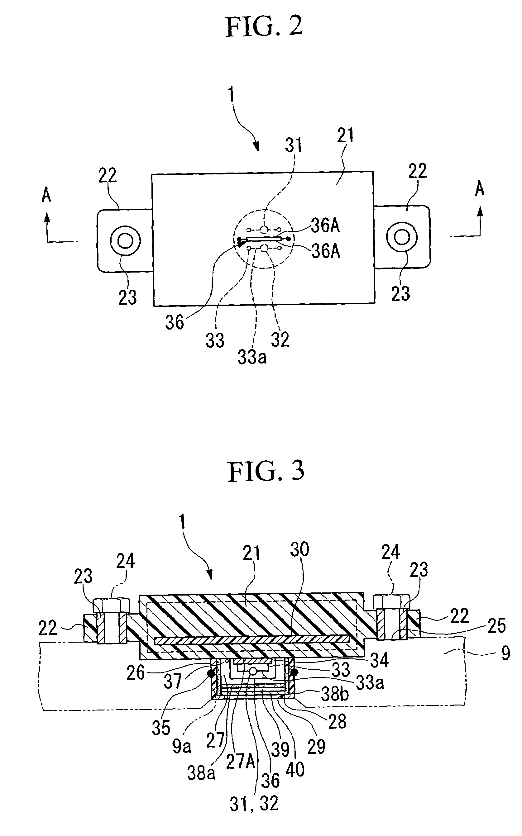
[0029]Hereinafter, a gas sensor according to one embodiment of the present invention will be explained with reference to the figures.

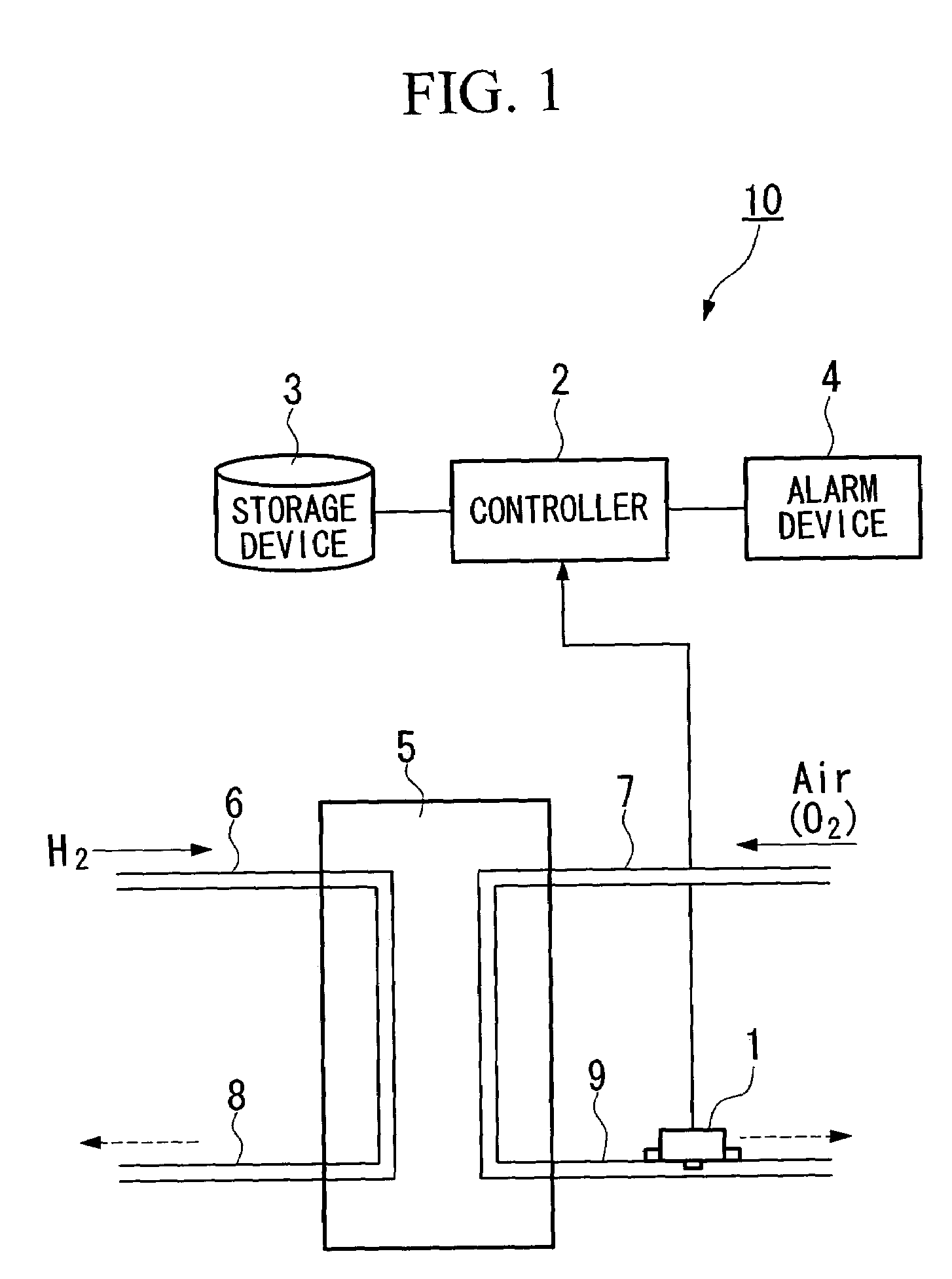
[0030]A gas sensor 1 according to the present embodiment is, for example, a hydrogen sensor for detecting hydrogen. As shown in FIG. 1, a fuel cell system 10 has a controller 2, a storage device 3, an alarm device 4, a fuel cell 5 which is a power source of a vehicle, and pipes 6, 7, 8, and 9 which are connected to the fuel cell 5 and transfer reaction gases to the fuel cell 5. In the fuel cell system 10, the gas sensor 1 is provided to the outlet side pipe 9 on an oxygen electrode side, and confirms that the hydrogen is not discharged through the outlet side pipe 9.

[0031]The controller 2 is connected to the gas sensor 1 attached to the outlet side pipe 9 on the oxygen electrode side. The controller 2 determines whether any abnormalities have occurred in the fuel cell 5 based on a comparison result of, for example, a detection signal outputted from the...


PUM

PropertyMeasurementUnit
electrical resistanceaaaaaaaaaa
temperatureaaaaaaaaaa
humidityaaaaaaaaaa

Abstract

A gas sensor includes a gas detection chamber into which a detection gas is introduced, a detecting element and a compensating element each disposed in the gas detection chamber, a detection device which detects the concentration of a detection target gas contained in the detection gas, in accordance with a difference in electrical resistance values between the detecting element and the compensating element, and a dehumidifying element which is provided in the gas detection chamber, and reversibly absorbs water contained in the detection gas and drains off the water absorbed in the dehumidifying element.

Description

BACKGROUND OF THE INVENTION[0001]Priority is claimed on Japanese Patent Application No. 2004-257137, filed Sep. 3, 2004, the contents of which are incorporated herein by reference.FIELD OF THE INVENTION[0002]The present invention relates to a gas sensor such as a gas-contact combustion-type hydrogen sensor, and a control method therefor.DESCRIPTION OF RELATED ART[0003]Conventionally, a solid high-polymer membrane-type fuel cell is provided with a cell wherein a solid high-polymer electrolytic membrane is sandwiched between a fuel electrode and an oxygen electrode, and a plurality of cells are configured in a layered stack (hereinafter referred to as a fuel cell). In the fuel cell, hydrogen is supplied to the fuel electrode as fuel, and air is supplied to the oxygen electrode as oxidant, and hydrogen ions produced at the fuel electrode due to a catalytic reaction pass through the solid high-polymer electrolytic membrane and migrate to the oxygen electrode, so that electricity is gene...

Claims


Application Information

Patent Timeline
Patent Type & Authority Patents(United States)
IPC IPC(8): G01N25/18
CPCG01N33/0011G01N33/006G01N33/005
Inventor OISHI, HIDETOSHIINOUE, HIROTOSHISASAKI, TAKASHISAITO, TAKASHI
Owner HONDA MOTOR CO LTD
Why Eureka
Try Eureka