Heat exchanger

a technology of heat exchanger and heat exchanger body, which is applied in the direction of indirect heat exchanger, light and heating apparatus, refrigeration components, etc., can solve the problem of becoming somewhat difficult to fabricate the members constituting, and achieve the effect of improving productivity

Inactive Publication Date: 2008-09-02
ZEXEL VALEO CLIMATE CONTROL CORP SAITAMA
View PDF14 Cites 10 Cited by
  • Summary
  • Abstract
  • Description
  • Claims
  • Application Information

AI Technical Summary

Benefits of technology

[0011]A rationally configured heat exchanger is obtained by the present invention. In other words, the heat exchanger of the present invention has the pressure resistance of the tank improved by dividing the interior of the tank into the plural hollow portions.
[0031]According to the present invention, a rationally configured heat exchanger can be obtained. Specifically, the hollow portions in the tanks are divided into prescribed spaces by the partition members. And, the projections of the partition members inserted through the holes of the plate bodies and the projections of the partition members inserted through the holes of the tank members are caulked, so that the plate bodies, the tank members and the partition members can be assembled firmly. Thus, the productivity can be improved furthermore.

Problems solved by technology

Therefore, it becomes somewhat difficult to fabricate the members constituting them, and it is desired that the individual component members are fabricated more efficiently at a heat exchanger manufacturing site.

Method used


Image

  • Heat exchanger
  • Heat exchanger
  • Heat exchanger

Examples


Embodiment Construction

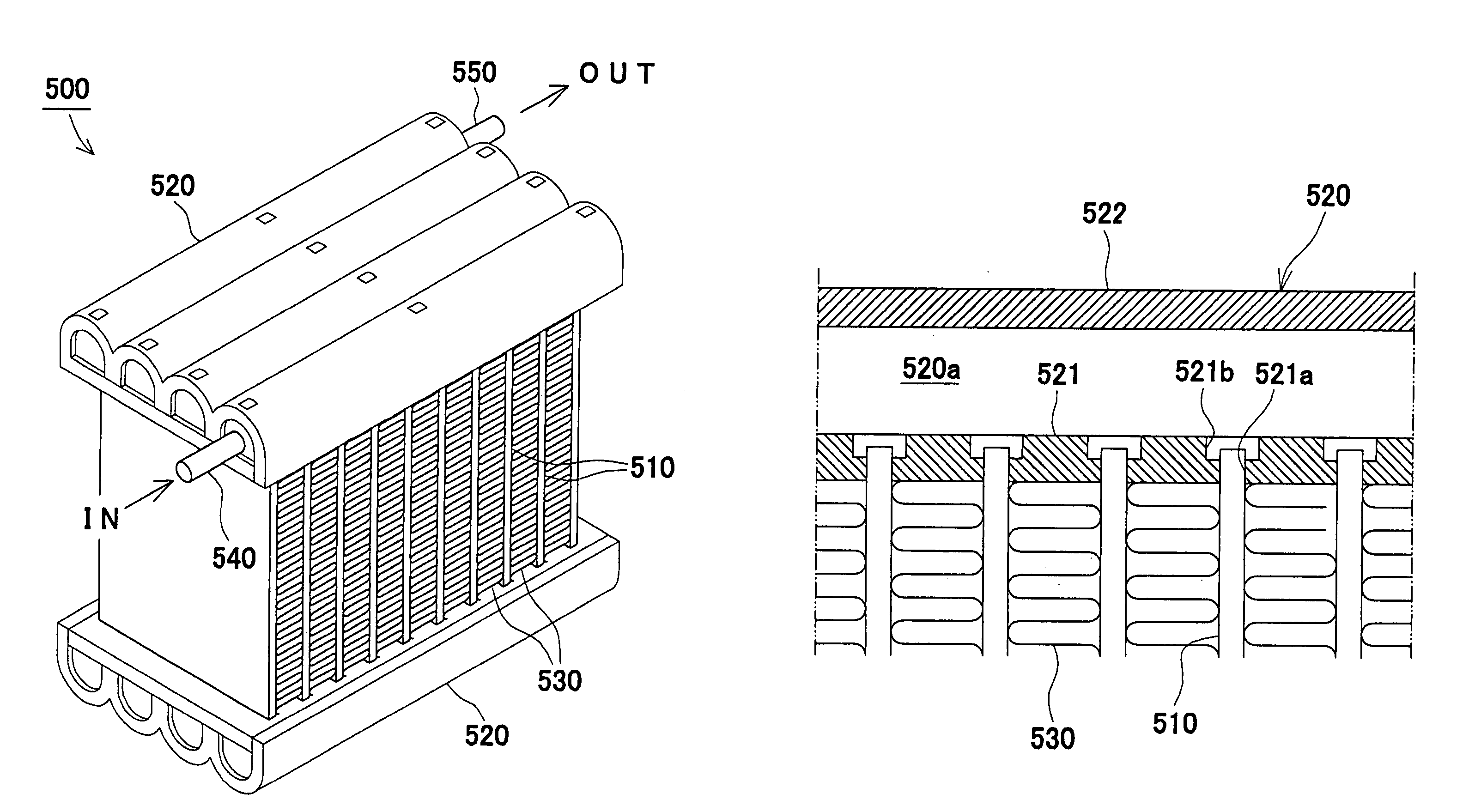
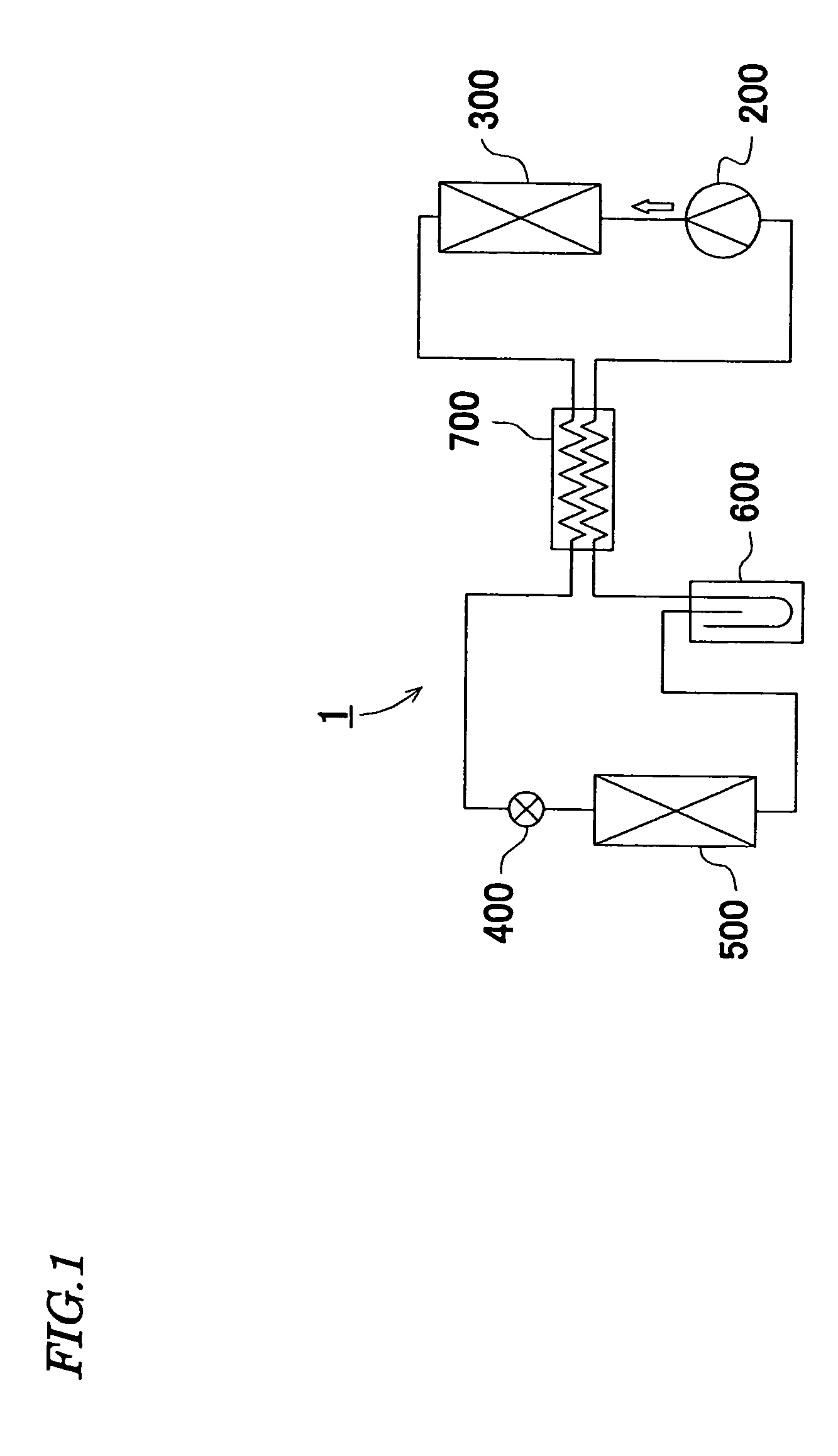
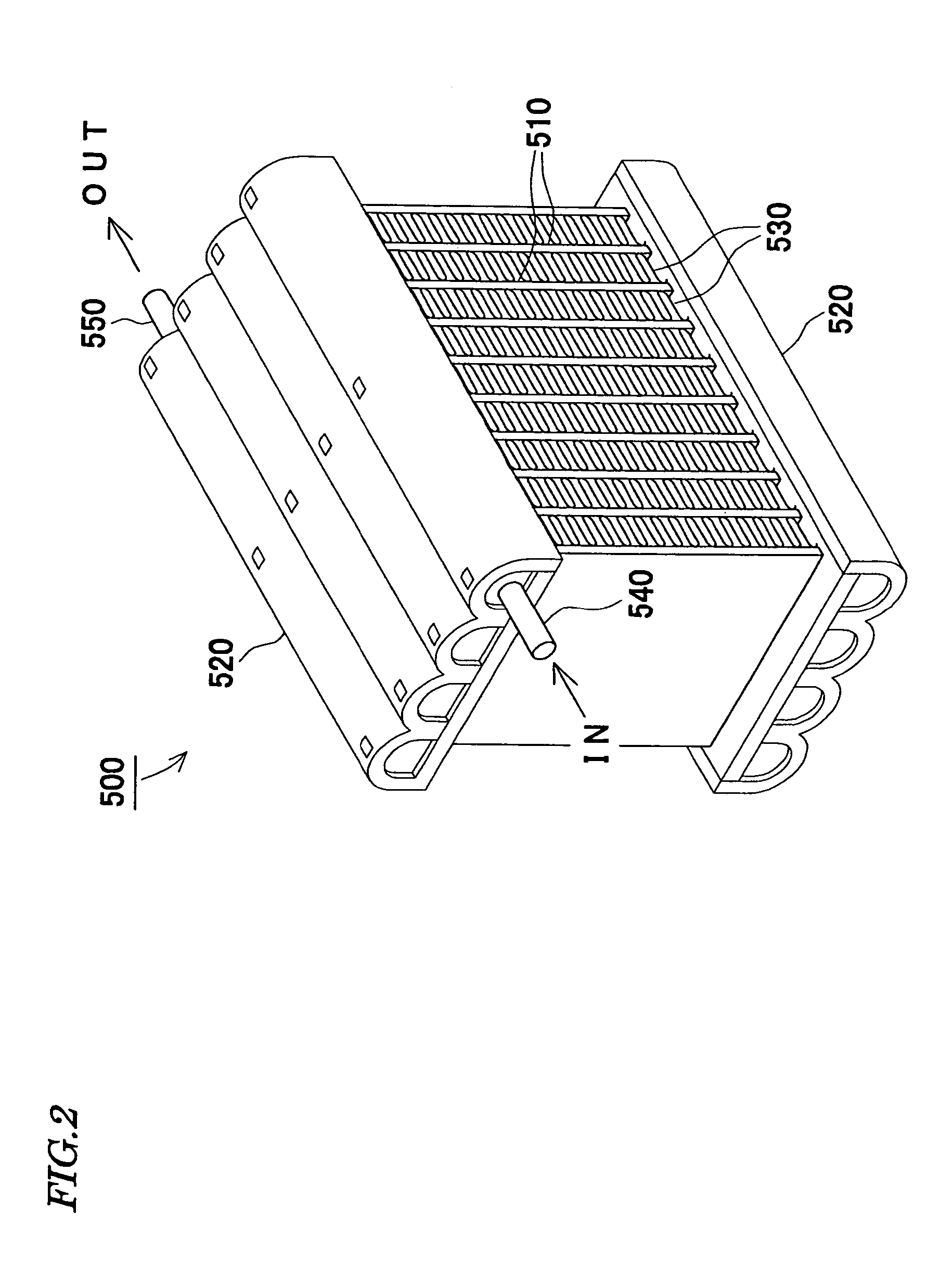
[0046]An embodiment of the present invention will be described in detail with reference to the drawings. A refrigerating cycle 1 shown in FIG. 1 is a refrigerating cycle for in-car air conditioning mounted on an automobile. This refrigerating cycle 1 is provided with a compressor 200 for compressing a refrigerant, a radiator 300 for cooling the refrigerant compressed by the compressor, an expansion valve 400 for expanding by decompressing the refrigerant cooled by the radiator 300, an evaporator 500 for evaporating the refrigerant decompressed by the expansion valve 400, an accumulator 600 for separating the refrigerant flowing out of the evaporator 500 into a gas layer and a liquid layer and feeding the gas layer refrigerant to the compressor 200, and an inner heat exchanger 700 for heat-exchanging between the refrigerant on a high-pressure side and the refrigerant on a low-pressure side to improve the efficiency of the cycle. CO2 is used as the refrigerant, and a supercritical ref...


PUM


Abstract

A heat exchanger for a supercritical refrigerating cycle, comprising tubes 510 and tanks 520 which have plural hollow portions 520a and slots 521a for insertion of the ends of the tubes formed, wherein a sectional outline of the hollow portions of the tanks has an approximately semicircular shape with a side corresponding to the diameter directed to the side of the slots. And, the partition members each 523 is disposed between the plate bodies 521 and the tank member 522. The tanks are formed by assembling plate bodies 521 with slots formed and tank members 522 with plural curves formed to configure hollow portions, and the plate bodies are provided with communicating recesses 521b for communicating plural hollow portions. Besides, the partition members 523 for division of the hollow portions are disposed between the plate bodies and the tank members, holes 521c, 522a are formed in required portions of the plate bodies and the tank members, and plural projections 523a to be inserted through the individual holes are formed on the partition members and caulked after being inserted through the holes.

Description

TECHNICAL FIELD[0001]The present invention relates to a heat exchanger for a refrigerating cycle having a pressure of exceeding the critical point of a refrigerant on the high-pressure side.BACKGROUND ART[0002]As a heat exchanger such as a radiator, an evaporator or the like used for the refrigerating cycle, one provided with tubes for flowing a refrigerant and tanks with slots formed for insertion of the tube ends is known. The refrigerant is taken from a tank into the interior, performs heat exchange with heat conducted to the tubes and is discharged outside from the tank.[0003]As the refrigerant for the refrigerating cycle, a fluorocarbon refrigerant including hydrochlorofluorocarbon has been used extensively. But it is now being replaced with CO2 considering the global environment in these years.[0004]A refrigerating cycle using CO2 as the refrigerant has a very high inside pressure as compared with the refrigerating cycle using a fluorocarbon refrigerant, and particularly a pre...

Claims


Application Information

Patent Timeline
Patent Type & Authority Patents(United States)
IPC IPC(8): F28F9/02F25B39/02F28D1/053F28F1/02
CPCF25B39/02F28D1/05391F28F9/0204F28F1/022F28F1/025F25B2309/061F28D2021/0071
Inventor TAKANO, AKIHIKO
Owner ZEXEL VALEO CLIMATE CONTROL CORP SAITAMA
Why Eureka
Try Eureka