Pipe mounting apparatus and method of use

Inactive Publication Date: 2008-09-02
INTENCITY LIGHTING
View PDF4 Cites 3 Cited by
  • Summary
  • Abstract
  • Description
  • Claims
  • Application Information

AI Technical Summary

Benefits of technology

[0013]Aspects of the present invention are generally directed to an internally expanding and locking mechanism that installs inside of the pipe stub of a typical outdoor lighting pole and expands with locking teeth to grasp the inner walls of the pipe mast or stub. An advantage taught by the present invention is the single point tightening method that permits the installer to relatively easily support the luminaire while securing it to the pipe stub or mast in a way that consistently conforms to mounting tension specification and thereby comply with standard wind load testing regardless of the pipe diameter and wall thickness. Another advantage of the present invention is the expansible nature of the mechanism that inherently provides a proper fit and registration to all pipe sizes ordinarily found in the field. Yet another advantage of the present invention is the pipe closure feature of the expanding mechanism that also inherently protects the luminaire from insect and weather intrusion for virtually any of the available pipe sizes, and which also adds further mechanical rigidity to the mounting. While the exemplary embodiment of the invention is shown and described in the context of mounting a luminaire to a conventional outdoor lighting pole, it will be appreciated by those skilled in the art that numerous other mounting applications, both of the pipe or other support and of the device to be mounted, are possible in the present invention without departing from its spirit and scope.

Problems solved by technology

In the typical application, electrical wires also pass through the pipe stub to connect within the luminaire after the luminaire is secured to the fitting, creating other mounting and sealing challenges.
Each of these previously described installation scenarios in the exemplary context of outdoor pole lighting is an awkward situation for an installer in a lift or bucket truck and as a result sometimes the installation is completed hastily without properly and evenly securing the mount.
The inconsistency in mounting integrity is demonstrated in practice with the prior art systems when moderate winds can weaken or remove some luminaires and not others despite wind tunnel test results showing sustainability.
Integrity may be further compromised if the clamp forces are not even or centered on the pipe to the manufacturer's recommendations.
Luminaire attitude or vertical angle adjustment is affected by the pipe stub position in the clamp method or flange screw methods in each of the aforementioned systems; therefore, when a non-zero angle of luminaire attitude adjustment is set, that can and often does adversely affect installation integrity.
The prior art described above teaches luminaire mounting systems that can be installed in various pipes and pipe stubs, but does not teach an apparatus and method including a single tightening point toward the front of the luminaire and thus facing in the direction of the installer and such a system that inherently closes the pipe against the luminaire regardless of the pipe size so as to prevent the intrusion of insects, small animals and weather.

Method used


Image

  • Pipe mounting apparatus and method of use
  • Pipe mounting apparatus and method of use
  • Pipe mounting apparatus and method of use

Examples


Embodiment Construction

[0019]The above described drawing figures illustrate aspects of the invention in at least one of its exemplary embodiments, which are further defined in detail in the following description.

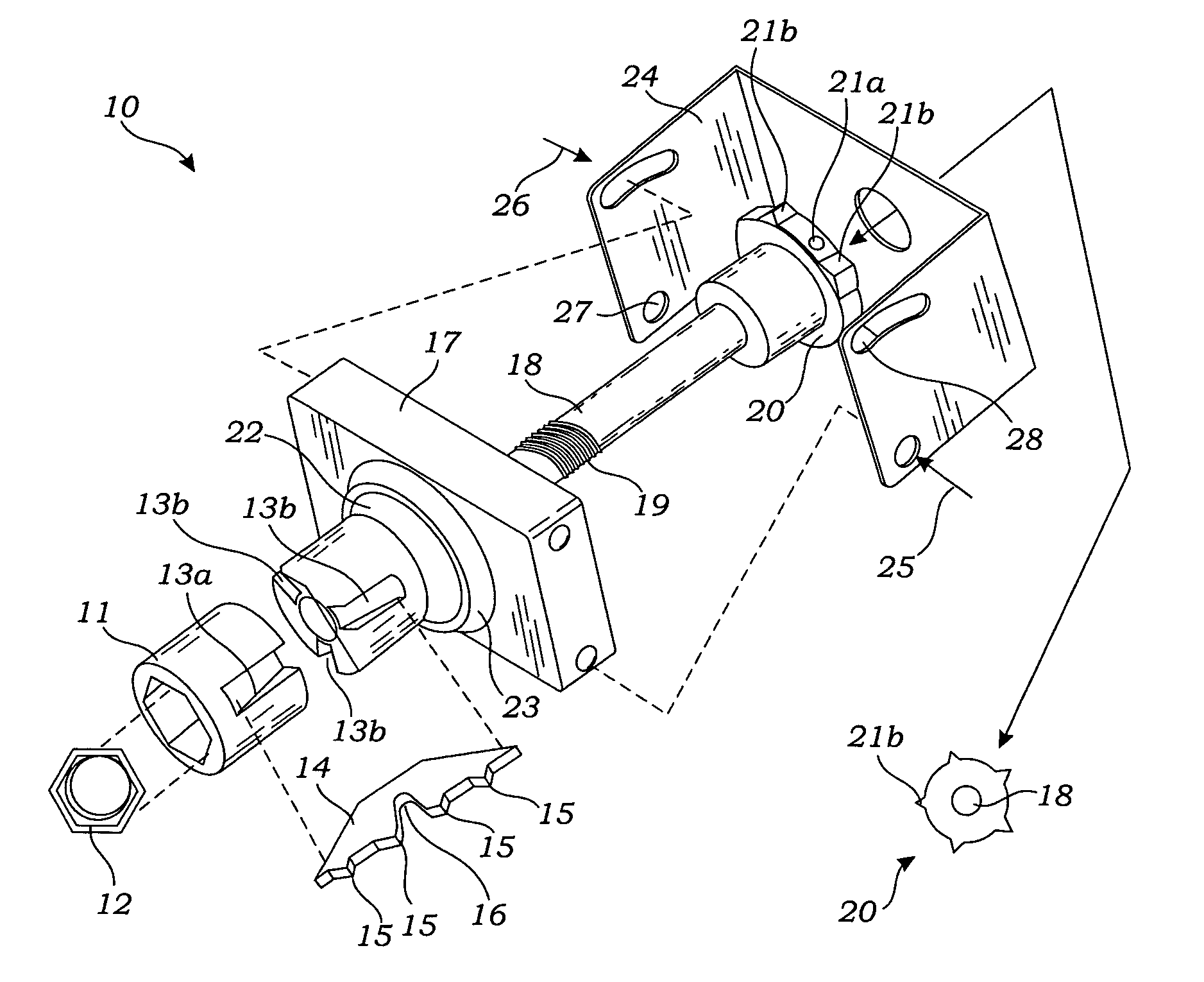
[0020]In FIG. 1 there is illustrated an exploded view of an exemplary embodiment of the pipe mounting apparatus 10 of the present invention. The pipe mounting apparatus generally comprises four primary components, including a ramp nut 11 that abuts a swivel base 17 when both have clamp screw 18 inserted through their respective center holes. The assembly of these components is held intact with mounting nut 12 when threaded onto the threads 19 that are cut into the end of the clamp screw 18 opposite the swivel base 17, the mounting nut 12 being seated and keyed within a corresponding recess in the free end of the ramp nut 11. It should be clear to the reader that with the mounting nut 12 so threaded on the clamp screw 18 and secured against rotation by being seated within the ramp nut 11, more or l...


PUM


Abstract

An internally expanding and locking apparatus for installing inside the pipe stub of a typical outdoor lighting pole and expanding with locking teeth to grasp the inner walls of the pipe stub, the apparatus including a swivel base, a clamp screw inserted through the swivel base, a ramp nut passing over the clamp screw so as to be positioned offset from the swivel base, and a mounting nut threadably installed on the clamp screw and configured to engage the ramp nut so as to control the position of the ramp nut relative to the swivel base as the clamp screw is rotated during use of the pipe mounting apparatus.

Description

RELATED APPLICATIONS[0001]This application claims priority and is entitled to the filing date of U.S. Provisional application Ser. No. 60 / 716,206 filed Sep. 12, 2005, and entitled “Luminaire Mounting System with Single Tightener.” The contents of the aforementioned application are incorporated by reference herein.INCORPORATION BY REFERENCE[0002]Applicants hereby incorporate herein by reference any and all U.S. patents and U.S. patent applications cited or referred to in this application.BACKGROUND OF THE INVENTION[0003]1. Field of the Invention[0004]Aspects of this invention relate generally to an apparatus and method for mounting a device to a pole or other structure having an existing pipe stub, and more particularly to such an apparatus and method for attaching luminaries to new or existing poles for particular lighting applications.[0005]2. Description of Related Art[0006]Pre-existing light poles or other supports and the pipes or pipe stubs extending therefrom on which a partic...

Claims


Application Information

Patent Timeline
IPC IPC(8): B42F13/00
CPCF21V21/116F21V27/00F21W2131/10
Inventor BRUCK, MICHAEL RAYMONDMULLINS, PATRICK STUART
Owner INTENCITY LIGHTING
Why Eureka
Try Eureka