Small double-locking waterproof connector

a waterproof connector, double-locking technology, applied in the direction of coupling device connection, coupling base/case, securing/insulating coupling contact member, etc., can solve the problem of adding an additional waterproofing structure, and achieve the effect of fine waterproof function

Inactive Publication Date: 2008-09-02
AUTONETWORKS TECH LTD +2
View PDF13 Cites 18 Cited by
  • Summary
  • Abstract
  • Description
  • Claims
  • Application Information

AI Technical Summary

Benefits of technology

[0010]However, the addition of such retainer insertion hole and retainer enlarges and complicates the structure of the connector, and increases passages allowing immersion of water into the female housing 112, thus causing a disadvantage that another structure for waterproofing is required to be added.
[0011]In view of such circumstances, the technical object of the present invention is to enable double-locking of female terminals without making a whole connector be larger in size or complicating a structure thereof while maintaining a fine waterproof function.
[0013]In this configuration, when the seal member holder is completely attached to the female housing in the state where each of the female terminals is inserted to each of the terminal accommodating chamber of the female housing and locked by the terminal locking portion, the waterproof seal member retained by the seal member holder comes in close contact with the front surface of the female housing, and the double-locking portion of the seal member holder pursues double-locking of the female terminal in the state of being placed into the female housing from the front side. Then, the male terminal on the side of the male connector is inserted into the through hole of the waterproof seal member and the male terminal insertion hole on the back side, to make the electric connection portion of the male terminal fit into the female terminal. This allows the terminals to electrically communicate with each other, and makes a close contact between the outer surface of the projection of the male housing covering the rear portion of the electric connection portion of the male terminal and the inner surface of the through hole of the waterproof seal member to waterproof each terminal individually.
[0014]In other words, this configuration gives the seal member both the function of retaining the waterproof seal member and the function of pursuing the double-locking of the female terminal to enable the double-locking of the female terminal without making a whole connector larger in size or complicating a structure thereof while maintaining a fine waterproof function.

Problems solved by technology

However, the addition of such retainer insertion hole and retainer enlarges and complicates the structure of the connector, and increases passages allowing immersion of water into the female housing 112, thus causing a disadvantage that another structure for waterproofing is required to be added.

Method used


Image

  • Small double-locking waterproof connector
  • Small double-locking waterproof connector
  • Small double-locking waterproof connector

Examples


Embodiment Construction

[0024]A preferred embodiment of the present invention will be described with reference to the drawings.

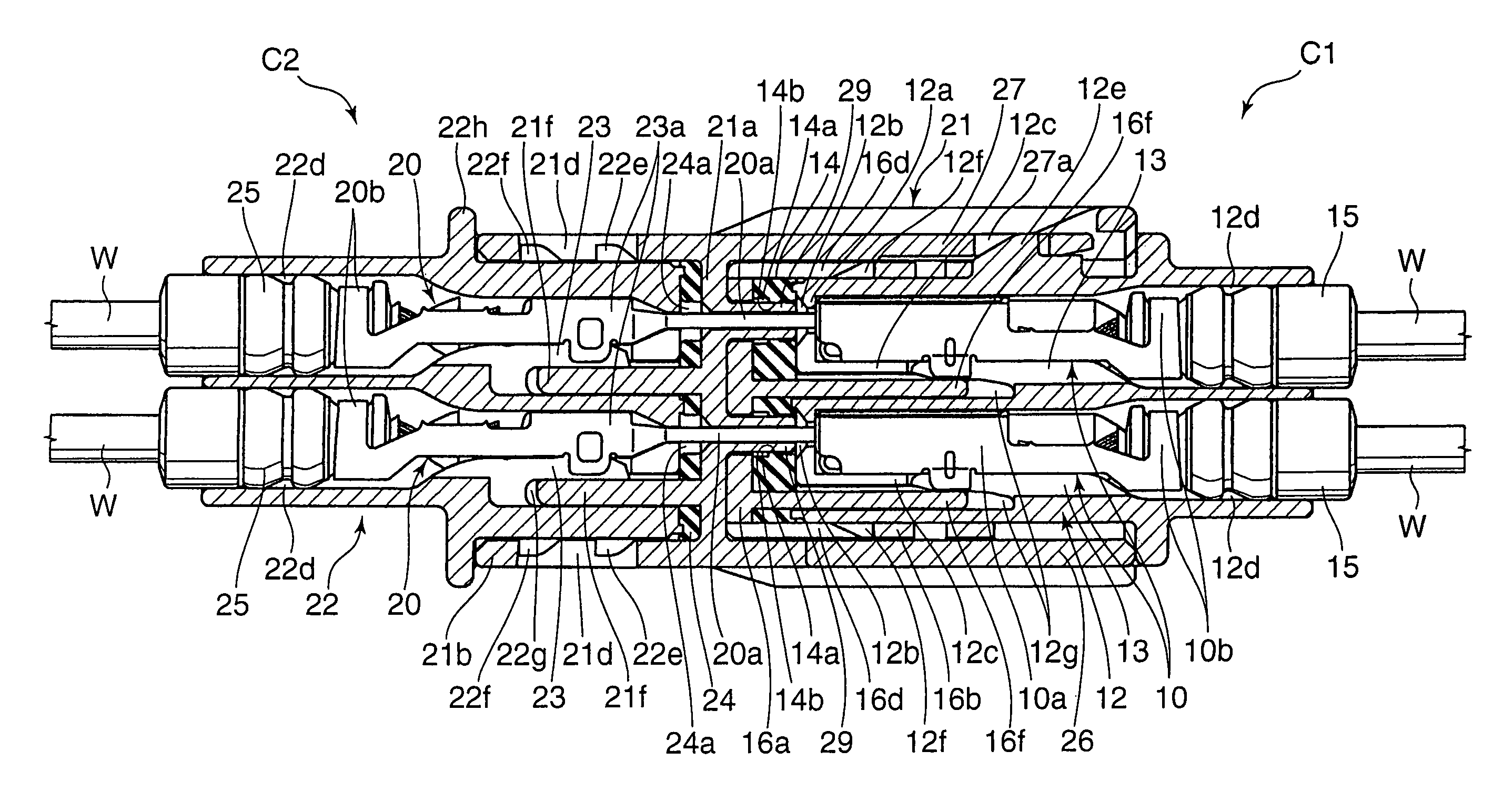
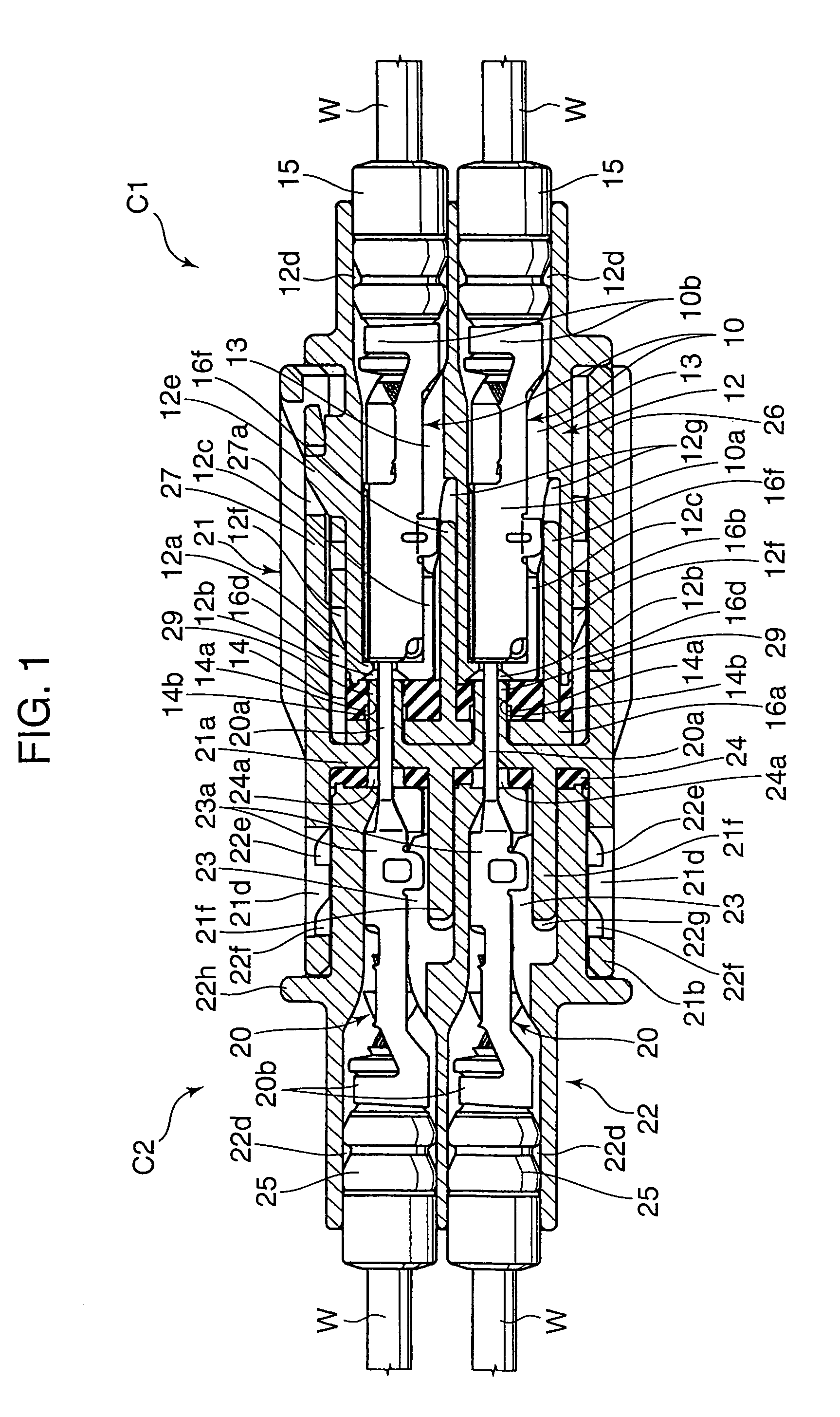
[0025]The waterproof connector shown in FIG. 1 includes a waterproof female connector C1 (hereinafter, simply referred to as “female connector C1”) in which a plurality of female terminals 10 are retained by a female housing 12, and a waterproof male connector C2 (hereinafter, simply referred to as “waterproof male connector C2”) in which male terminals 20 to fit into the respective female terminals 10 are retained by the male housings 21, 22. Specific configurations and assembling procedures for the connectors C1, C2 are as follows.

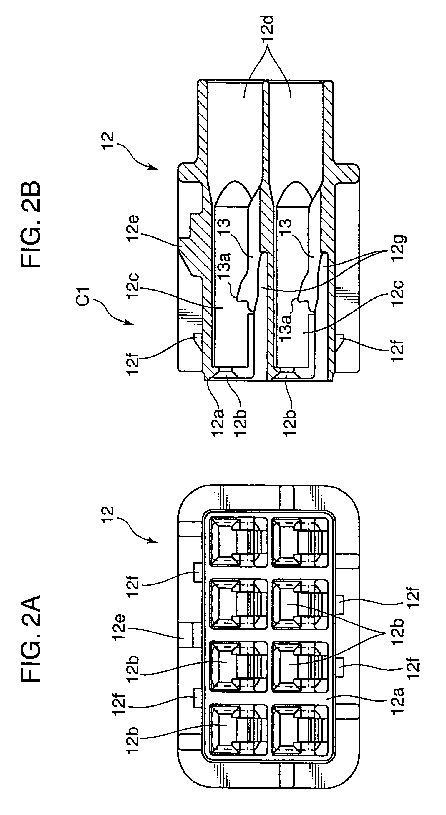
1) Specific Configuration of the Female Connector C1

[0026]Each female terminal 10 of the female connector C1 integrally includes a female type electric connection portion 10a and a barrel portion 10b formed on the rear side. The barrel portion 10b is bent to be crimped onto an end of an electric wire W. Further, on the immediate rear side from the femal...


PUM


Abstract

A object of the present invention is to enable a double-locking of female terminals without making a whole connector larger in size or complicating a structure thereof while maintaining fine waterproof function. A female connector includes a female housing for retaining a female terminal and a seal member holder. The seal member holder retains a seal member having through holes. When the seal member holder is completely attached to the female housing, the seal member comes in close contact with a front surface of the female housing. In this state, a male terminal of a male connector fits into the female terminal so that a projecting portion of the female connector comes in close contact with an inner surface of the through hole to make terminals waterproof individually. Further, the seal member holder is provided with a double-locking piece in, which pursues the double locking of the female terminal in the female housing at the time of the complete attachment.

Description

[0001]This is a National Stage of Patent Application No. PCT / JP2005 / 021004 filed Nov. 16, 2005, which claims the benefit of U.S. Japanese Patent Application No. 2004-333422 filed Nov. 17, 2004. The disclosures of the prior applications are hereby incorporated by reference herein in their entirety.TECHNICAL FIELD[0002]The present invention relates to a waterproof connector having a function to waterproof each terminal individually.BACKGROUND ART[0003]It is generally recognized that a conventional waterproof connector is provided with a seal member surrounding a plurality of terminal accommodating chambers and collectively waterproofs the entire terminal accommodating chambers with the seal member. However, such configuration requires a space for mounting the seal member to be secured on further exterior side from each terminal accommodating chamber, and this causes a disadvantage that a size of the whole connector becomes larger in a direction perpendicular to an axial direction of t...

Claims


Application Information

Patent Timeline
Patent Type & Authority Patents(United States)
IPC IPC(8): H01R13/52
CPCH01R13/5221H01R13/4365H01R13/4223
Inventor TSUJI, TAKESHIOKAMOTO, MICHIAKIHIRAI, HIROKIYOSHIOKA, CHIKAHIRO
Owner AUTONETWORKS TECH LTD
Why Eureka
Try Eureka