Waste heat collecting system having expansion device

a technology of expansion device and heat collection system, which is applied in the direction of engine components, mechanical equipment, machines/engines, etc., can solve the problems of reducing the output of the expansion device, unable to obtain the necessary amount of work volume, and generating losses by such over expansion, etc., to achieve the effect of increasing the complexity of the expansion device and increasing the cos

Inactive Publication Date: 2007-10-04
DENSO CORP +1
View PDF19 Cites 64 Cited by
  • Summary
  • Abstract
  • Description
  • Claims
  • Application Information

AI Technical Summary

Benefits of technology

[0017] The present invention is made in view of the above problems. An object of the present invention is, therefore, to provide a waste heat collecting system having an expansion device, which is driven by the expansion of the refrigerant to generate the rotational driving force, wherein a loss to be caused by the over expansion of the refrigerant is suppressed without increasing a complicated structure of the expansion device and a cost increase.

Problems solved by technology

When the over expansion takes place, a loss is generated by such over expansion.
As a result, the output of the expansion device is decreased and the necessary amount of the work volume may not be obtained, when the actual temperature is higher than the ambient temperature for the proper expansion.
For example, in a system or an apparatus, in which a motor generator is driven by the expansion device, a necessary amount of electric power may not be generated due to the loss caused by the over expansion, when the ambient temperature is high, for example, during the summer season.
According to the above prior art, however, the expansion device becomes more complicated in structure, because the bypass passage and the valve device are provided in the expansion device.
And the cost of the expansion device is also increased.
In addition, a failure probability will be increased, in case that an additional device (the valve device) is provided.

Method used


Image

  • Waste heat collecting system having expansion device
  • Waste heat collecting system having expansion device
  • Waste heat collecting system having expansion device

Examples


first embodiment

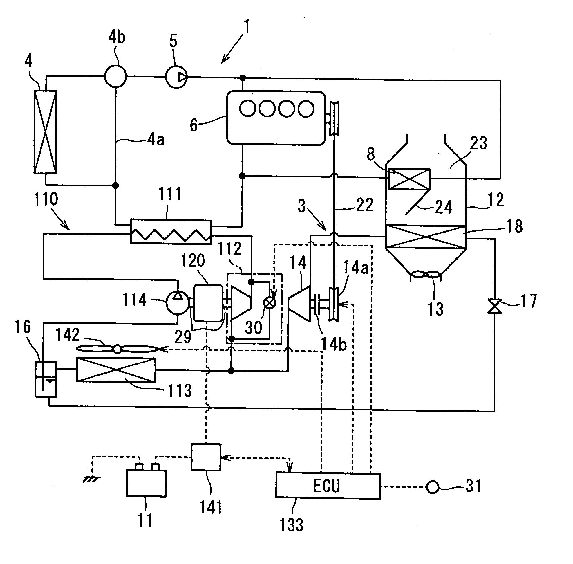
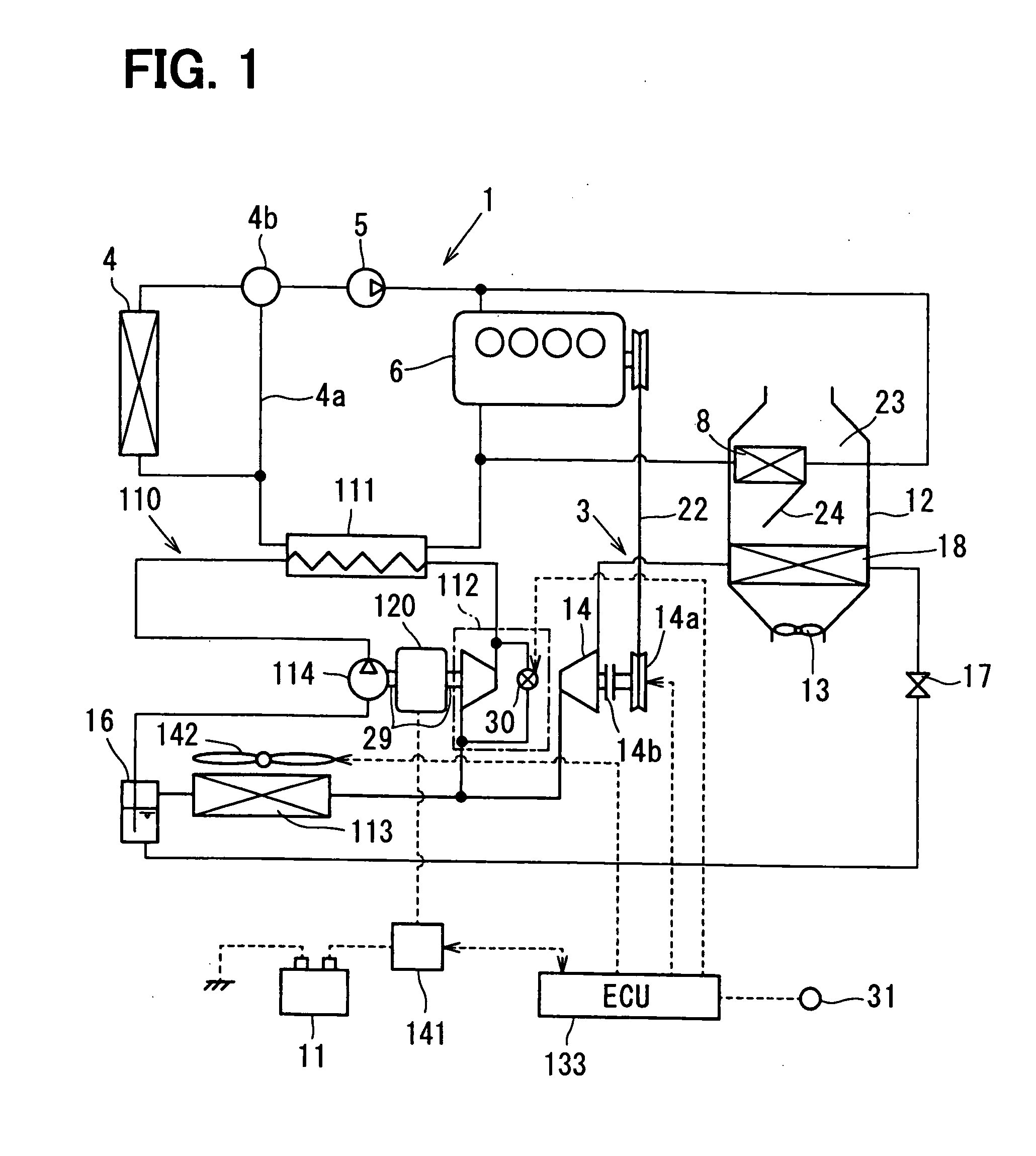
[0042] A system structure of a waste heat collecting apparatus will be explained with reference to FIG. 1. The waste heat collecting apparatus according to an embodiment of the present invention gets a rotational energy, by use of Rankine cycle 110, out of heat in engine cooling water (hot water) circulated in an engine cooling circuit 1, to generate electric power. As shown in FIG. 1, a part of the Rankine cycle 110 is commonly used in a refrigerating cycle 3 for an air conditioning apparatus mounted in an automotive vehicle.

[0043] The engine cooling circuit 1 has a main circuit, in which the engine cooling water is circulated from a radiator 4, a water pump 5, an engine (a water jacket), a heating device 111, and back to the radiator 4. The engine cooling circuit 1 has an air conditioning hot water circuit, in which the engine cooling water (hot water) is circulated from the engine (the water jacket), a heater core 8, and back to the engine. The heating device 111 is a component ...

second embodiment

[0150] A second embodiment of the present invention will be explained with reference to FIGS. 6 and 7. A structure will be explained with reference to FIG. 6. The second embodiment shows a control system for an expansion device, which is applied to an expansion device 112 to be used in Rankine cycle 110 to be mounted in an automotive vehicle.

[0151] The vehicle, to which the present invention is applied, is a general passenger car, which is equipped with a water-cooled internal combustion engine (not shown) as a driving source for a vehicle travel. An alternator 150 is mounted in the vehicle, which is driven by the engine to generate electric power. The electric power generated by the alternator 150 is charged into a battery 11 through an inverter 141, and the electric power charged in the battery 11 is supplied to vehicle electrical loads 160, such as head lamps, a wiper motor, an audio equipment, and so on.

[0152] The Rankine cycle 110 collects waste heat (thermal energy of engine...

third embodiment

[0174] A third embodiment of the present invention is shown in FIGS. 8 and 9. In the third embodiment, the condensing device 113 and the blower device 142 are formed as the means 140A for increasing the pressure difference ΔP. The same reference numerals are used in the third embodiment to designate the same or similar components and parts in the third embodiment.

[0175] The blower device 142 of the third embodiment is formed as an electrical blower device for blowing the cooling air to the condensing device 113, as shown in FIG. 8. A rotational speed of the electrical blower device 142 is controlled by the controller 133. An operation of the third embodiment will be controlled by a flow chart shown in FIG. 9. In FIG. 9, the steps S120 and S130 of FIG. 7 are replaced by steps of S120A and S130A.

[0176] When the controller 133 determines, at the step S110, that the pressure difference ΔP at the expansion device 112 is lower than the predetermined pressure difference ΔPth, the control...


PUM


Abstract

An object of the invention is to provide a waste heat collecting system having an expansion device, in which an over expansion of refrigerant is prevented so that a loss to be caused by the over expansion is eliminated. A volume ratio of expansion for the expansion device is selected at a value, at which proper expansion of the refrigerant is achieved when the pressure difference between the high pressure and the low pressure is minimum.

Description

CROSS-REFERENCE TO RELATED APPLICATION [0001] This application is based on Japanese Patent Application Nos. 2006-81426 filed on Mar. 23, 2006 and 2006-140295 filed on May 19, 2006, disclosures of which are incorporated herein by reference. FIELD OF THE INVENTION [0002] The present invention relates to a waste heat collecting system having an expansion device, which is driven to rotate by expansion of high-pressure and high-temperature refrigerant to generate rotational driving force. BACKGROUND OF THE INVENTION [0003] According to a conventional technology, in which a rotational force is obtained by use of waste heat generated in a vehicle, refrigerant is heated by a heating device by use of heat generated in the vehicle to produce high pressure refrigerant. The high pressure refrigerant is supplied to a high pressure chamber of an expansion device, so that an output shaft is rotated by pressure difference between the high pressure chamber and a low pressure chamber of the expansion...

Claims


Application Information

Patent Timeline
Patent Type & Authority Applications(United States)
IPC IPC(8): F01P3/22F01P11/00
CPCF01P3/20F01P9/06Y02T10/166F02G5/00F02G2260/00F01P2060/14Y02T10/12
Inventor TAKEUCHI, YASUHIROUTIDA, KAZUHIDEUNO, KEIICHIINABA, ATSUSHIOGAWA, HIROSHIASA, HIRONORIKISHITA, HIROSHI
Owner DENSO CORP
Why Eureka
Try Eureka