Supercharge Your Innovation With Domain-Expert AI Agents!

Solid floor board assembly with duct raceway cavity

a technology of floor board and raceway, which is applied in the direction of connecting contact member material, flooring, building roofs, etc., can solve the problems of poor workmanship quality, unsatisfactory appearance of finished floors, and expensive floor materials made of plastic tiles, ceramic tiles, etc., to enhance compressive strength and improve the outer look of the whole structure

Inactive Publication Date: 2008-09-02
CHEN CHIH JUNG
View PDF9 Cites 0 Cited by
  • Summary
  • Abstract
  • Description
  • Claims
  • Application Information

AI Technical Summary

Benefits of technology

"The present invention provides a solid floor board assembly with duct raceway cavity that can accommodate building ducts and piping equipment in a neat and orderly manner. The floor board assembly is clean and easy to assemble, and the raceways can be extended in all directions. The floor board assembly includes base blocks, layer plates, and floor boards, which are interconnected to form a solid structure. The hollow cavity between the base blocks and layer plates is covered with floor boards to improve the outer look of the structure. The floor board assembly has a high compressive strength and can be customized based on the needs of the owner. Several duct exits are provided on the surface of the floor board assembly to allow for extension of the raceway in any direction."

Problems solved by technology

It is very often that those expensive floor material made of tiles of plastic, ceramic, wood, marble or even carpet have to be removed and replaced with other materials wasting a lot of money in case the owner or dweller of the building is changed so as to meet the new owner's requirement or taste.
However, in addition to poor quality of workmanship, the random use of primitive accessories such as tie wires and nails, the appearance of finished floor has never been satisfactory.
But such floor board design inducted an in negligible problem of noisy echoing sound fed back from the cavity underneath the floor.
For these defects noticeable on the prior art, an improvement is seriously required.

Method used


Image

  • Solid floor board assembly with duct raceway cavity
  • Solid floor board assembly with duct raceway cavity
  • Solid floor board assembly with duct raceway cavity

Examples


Embodiment Construction

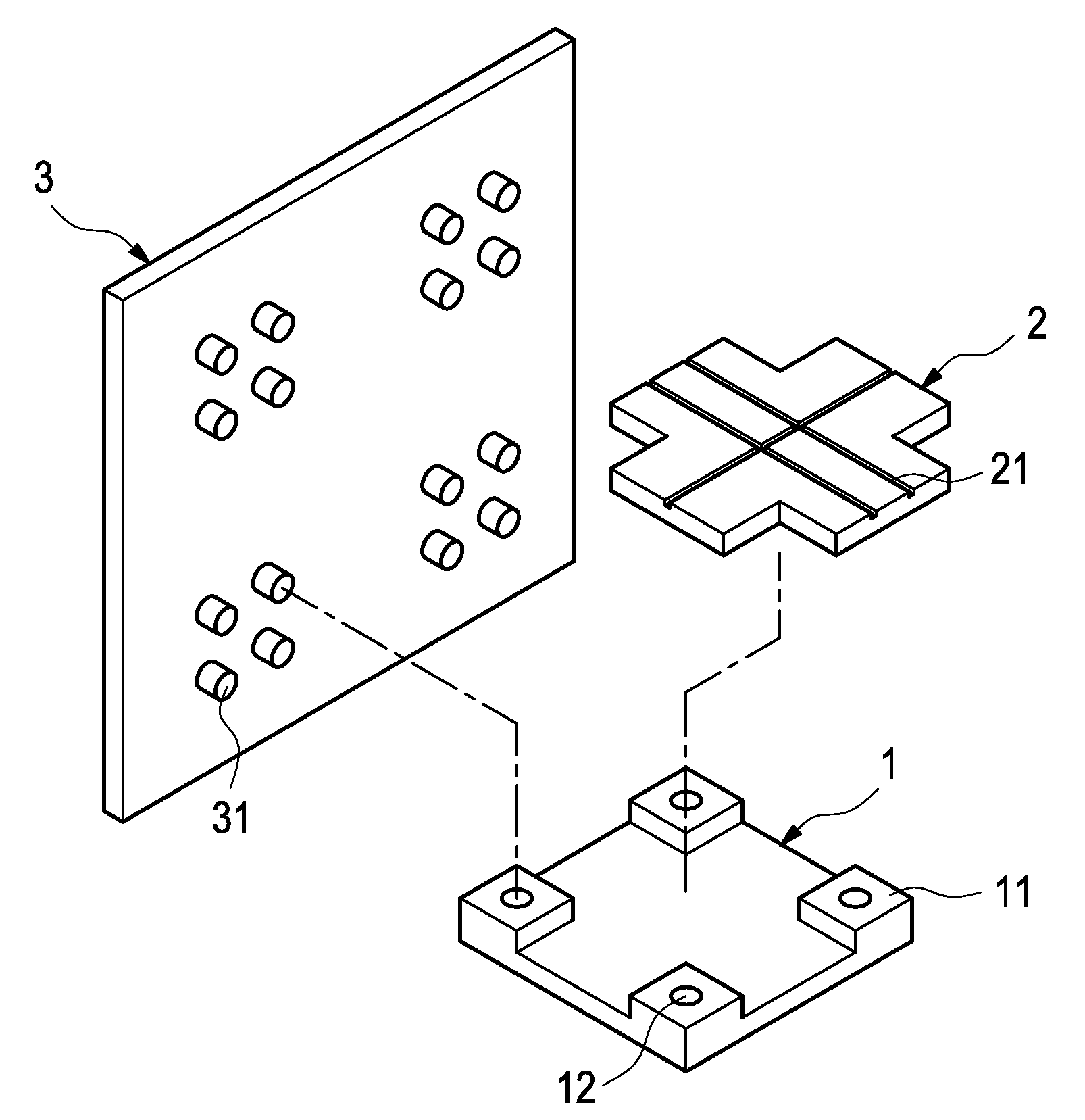
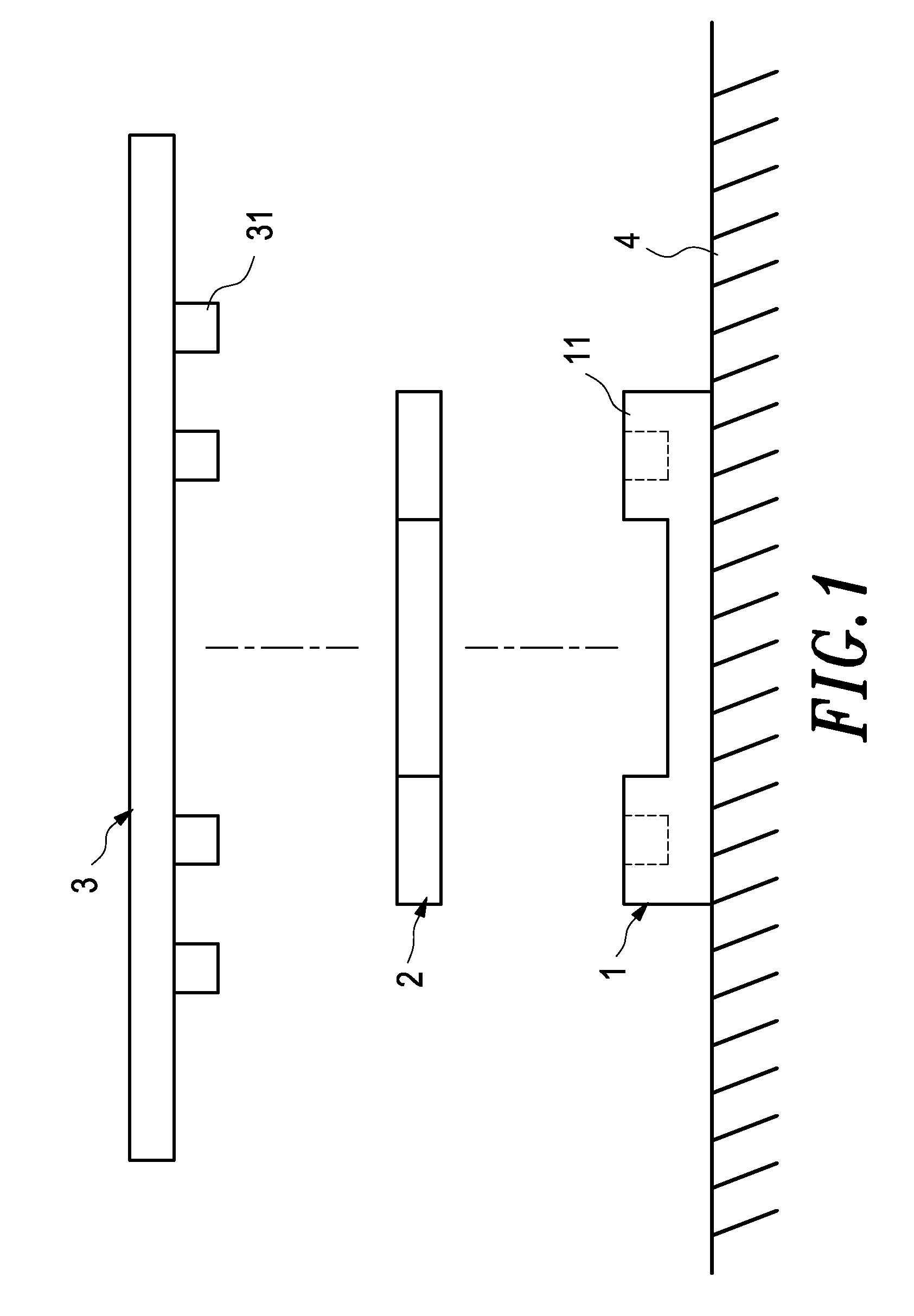
[0025]Referring to FIG. 1, which is an exploded view showing one unit piece of the present invention. The solid floor board assembly with duct raceway cavity is composed of a plurality of unit base block 1, unit layer plate 2, and unit floor board 3.

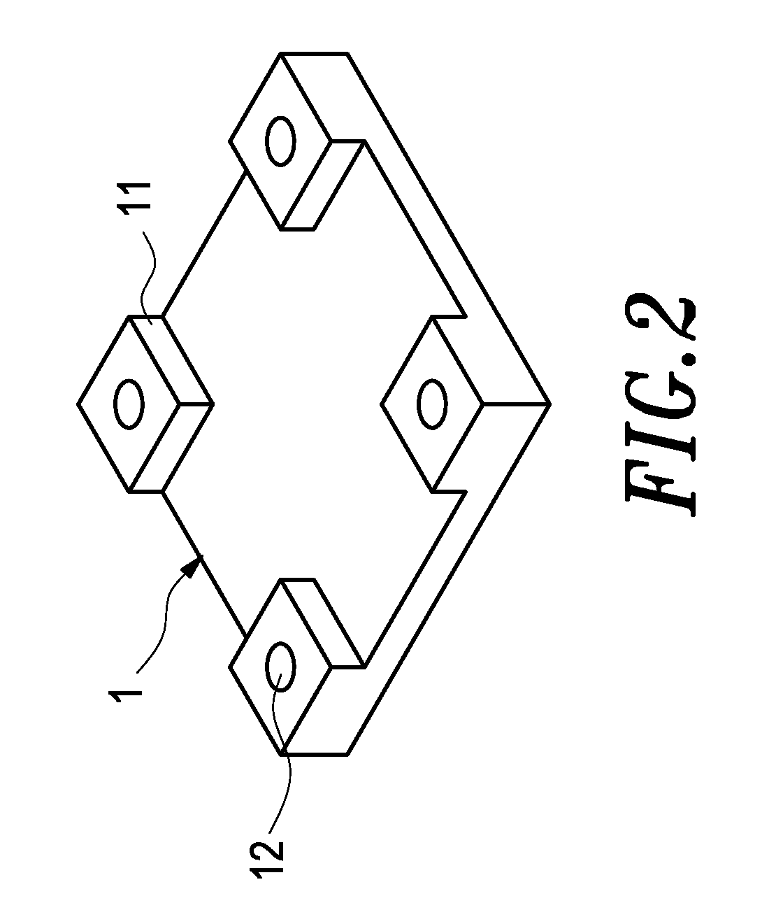
[0026]FIG. 2 and FIG. 3 are the perspective views of the base block and the layer plate respectively. Each base block 1 is provided with four stubs 11 at four corners thereof, and a recess 12 is formed on the top surface of each stub 11. The layer plate 2 is entrained on the base block 1 among four stubs 11 and can be formed into any desired configuration so as to partition the cavity between the base block 1 and the layer plate 2 in the transverse and longitudinal direction. The base block 1 is firmly sustained on the ground with screws, two-faced binder, liquid binder, or nails.

[0027]FIG. 4 is a perspective view of the floor board, and FIG. 5 is an exploded view for illustrating the structural relation among the component parts accordi...


PUM


Abstract

A solid floor board assembly with duct raceway is composed of a plurality of base blocks, layer plates, and floor boards. A hollow cavity is formed between the base blocks and the layer plates and is partitioned to accommodate a variety of wire ducts and conduit installations neatly and orderly in desired configuration, and the surface thereof is covered with the floor boards so as to further improve the appearance of the whole structure. The solidarity of structure ensures a high compressive strength, and the number of unit floor board for assembly, the size and the configuration is left to the decision of the building owner. Slip resistant stripes, flower-like striae or a picturesque pattern may be provided on the surface of the floor boards. Duct and conduit exits are provide on the surface of the floor boards for extension of wire ducts and conduit installation.

Description

BACKGROUND OF THE INVENTION[0001]1. Field of the Invention[0002]The present invention relates to solid floor board assembly with duct raceway cavity to accommodate various ducts and conduits necessary for installation of building facilities.[0003]2. Description of the Prior Art[0004]Interior decoration is necessary for all buildings including factory office, residential housing and hotel etc. It is very often that those expensive floor material made of tiles of plastic, ceramic, wood, marble or even carpet have to be removed and replaced with other materials wasting a lot of money in case the owner or dweller of the building is changed so as to meet the new owner's requirement or taste. And sometimes in such cases, the partition walls must be detached or removed to a new position in order to match the new interior design requiring large amount of labor.[0005]Modern buildings generally use assembly of layered floor board to avoid scratching its surface when moving furniture or other ...

Claims


Application Information

Patent Timeline
Patent Type & Authority Patents(United States)
IPC IPC(8): E04F15/024
CPCE04F15/02H02G3/383E04F15/02411Y10S439/925
Inventor CHEN, CHIH-JUNG
Owner CHEN CHIH JUNG
Features
  • R&D
  • Intellectual Property
  • Life Sciences
  • Materials
  • Tech Scout
  • Unparalleled Data Quality
  • Higher Quality Content
  • 60% Fewer Hallucinations
Learn More