Current control circuit with limiter, temperature control circuit, and brightness control circuit
a limiter and current control technology, applied in the direction of limiting amplitude without controlling loop, process and machine control, instruments, etc., can solve the problems of reducing size and cost, variating limiter voltage, etc., and achieve the effect of simple structur
- Summary
- Abstract
- Description
- Claims
- Application Information
AI Technical Summary
Benefits of technology
Problems solved by technology
Method used
Image
Examples
first exemplary embodiment
1. First Exemplary Embodiment
[0041]Embodiments of the present invention will be described with reference to the drawings. In each of the following embodiments, assume that an Op-Amp is an ideal Op-Amp, a voltage gain is sufficiently large, and each of an input offset voltage and an input bias current is sufficiently small and thus can be neglected. Although a power source voltage is set to +5 V, the present invention is not particularly limited to this voltage. Although a reference voltage Vr set as a limiter voltage is 2 V, Vr can be set to an arbitrary voltage within the power source voltage range of the Op-Amp. The same arbitrary setting can similarly be made in each of the following embodiments.
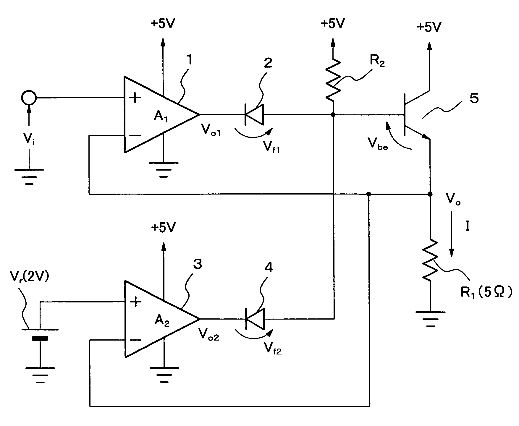
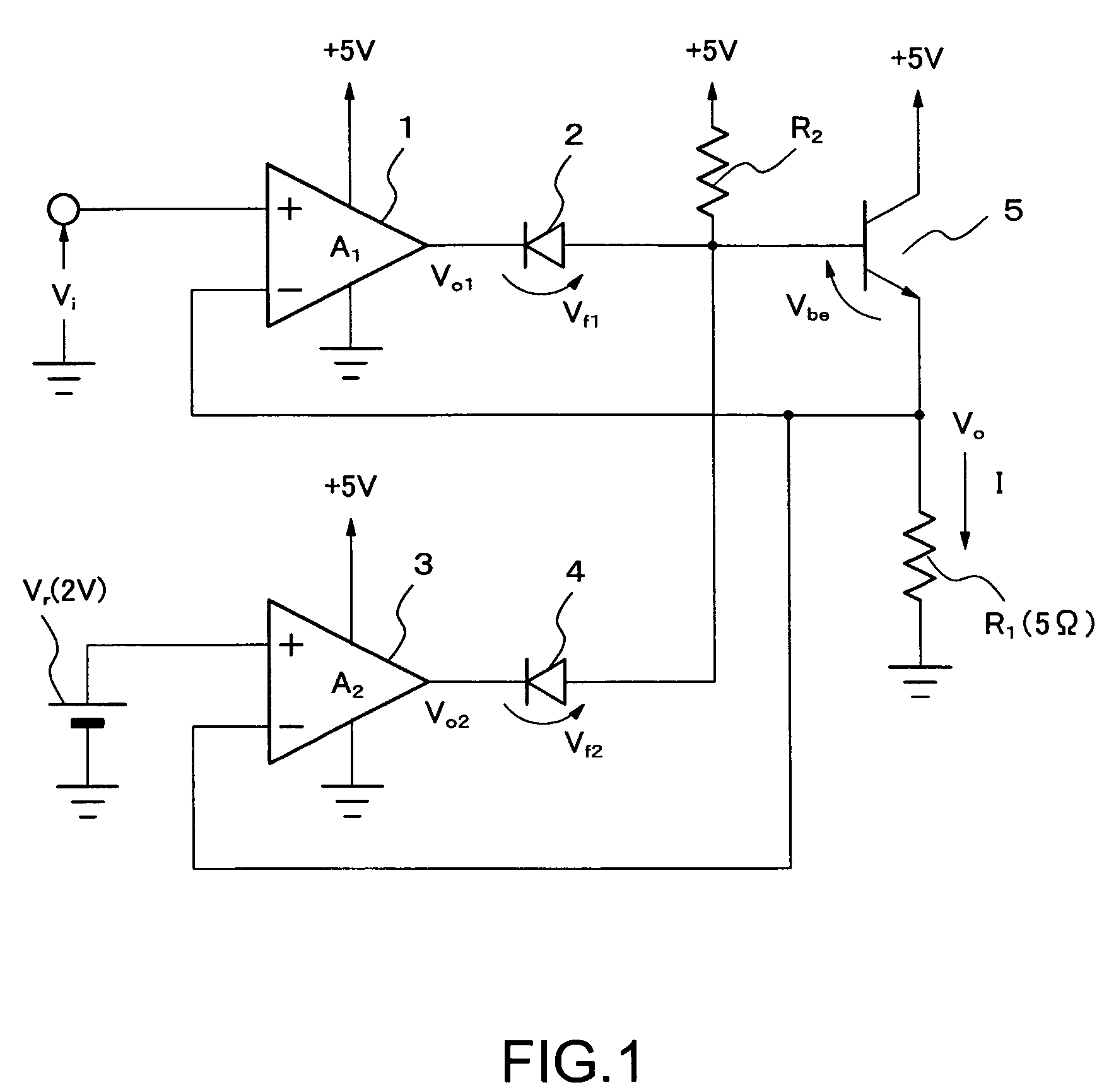
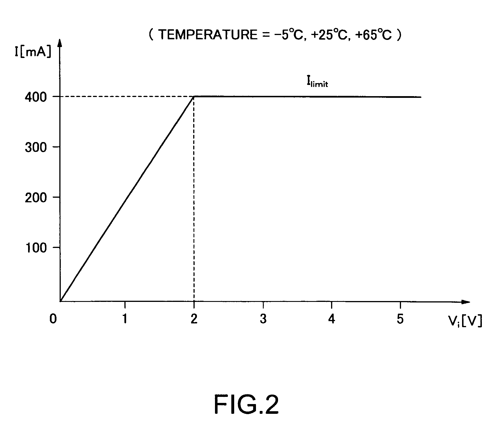
[0042]FIG. 1 is a circuit diagram showing a first embodiment of the present invention. A control input voltage Vi is connected to the non-inverting input of an Op-Amp 1. The output of the Op-Amp 1 is connected through diode 2 to the base input of an NPN transistor 5 composing the emitter ...
second exemplary embodiment
2. Second Exemplary Embodiment
[0070]In the first embodiment, the emitter follower is composed of the NPN transistor 5. The emitter follower can be composed of a PNP transistor. The transistor to be used is not limited to a bipolar transistor. It is apparent that a source follower composed of a field effect transistor including a MOS transistor may be used. At this time, the channel type of the field effect transistor may be an N-channel type or a P-channel type.
[0071]Next, an exemplary embodiment of the present invention in a case where the NPN transistor 5 is replaced by another type of transistor will be described.
[0072]FIG. 3 is a circuit diagram showing a second exemplary embodiment of the present invention. The NPN transistor 5 shown in FIG. 1 is replaced by an n-channel field effect transistor 8. The operation of a circuit according to the second embodiment will be described with reference to FIG. 3 and numerical expressions.
[0073]First, the operation of Op-Amp 1 will be descr...
third exemplary embodiment
3. Third Exemplary Embodiment
[0084]FIG. 4 is a circuit diagram showing a third exemplary embodiment of the present invention. The NPN transistor 5 shown in FIG. 1 is replaced by a PNP transistor 9. In the third exemplary embodiment, the connection direction of each of diode 2 and diode 4 is reversed to that in each of the first exemplary embodiment and the second exemplary embodiment. That is, the anode of diode 2 is connected with the output terminal of Op-Amp 1 and the cathode thereof is connected with the base of the PNP transistor 9. The anode of diode 4 is connected with the output terminal of the Op-Amp 3 and the cathode thereof is connected with the base of PNP transistor 9.
[0085]In the circuit shown in FIG. 4, when Vi is higher than Vr, diode 4 subjected to wired OR connection goes into the Off-state. Therefore, the feedback circuit of Op-Amp 3 is interrupted and the output thereof is blocked. On the other hand, because diode 2 goes into the On-state, negative feedback is ap...
PUM
 Abstract
Description
Claims
Application Information
 - R&D
- Intellectual Property
- Life Sciences
- Materials
- Tech Scout
- Unparalleled Data Quality
- Higher Quality Content
- 60% Fewer Hallucinations
Browse by: Latest US Patents, China's latest patents, Technical Efficacy Thesaurus, Application Domain, Technology Topic, Popular Technical Reports.
© 2025 PatSnap. All rights reserved.Legal|Privacy policy|Modern Slavery Act Transparency Statement|Sitemap|About US| Contact US: help@patsnap.com


