Light receiving circuit, semiconductor laser device, and optical pickup device

Inactive Publication Date: 2006-10-19
PANASONIC CORP
View PDF7 Cites 0 Cited by
  • Summary
  • Abstract
  • Description
  • Claims
  • Application Information

AI Technical Summary

Benefits of technology

[0037] The present invention aims at solving the aforementioned conventional problems and providing a light receiving circuit, a semiconductor laser device, and an optical pickup device, capable of preventing an output variation of the light receiving circuit caused by a change in ambient temperature, with a simple configuration.
[0038] The present invention is summarized in that a temperature coefficient of the light receiving circuit may be flattened by controlling

Problems solved by technology

The aforementioned conventional configuration, however, has following problems.
If the feedback is performed so as to emit the light at the power different from the desired power, supposing that the output from the light receiving circuit 100 has a negative temperature coefficient for example, when the temperature increases, the feedback is performed

Method used


Image

  • Light receiving circuit, semiconductor laser device, and optical pickup device
  • Light receiving circuit, semiconductor laser device, and optical pickup device
  • Light receiving circuit, semiconductor laser device, and optical pickup device

Examples


first embodiment

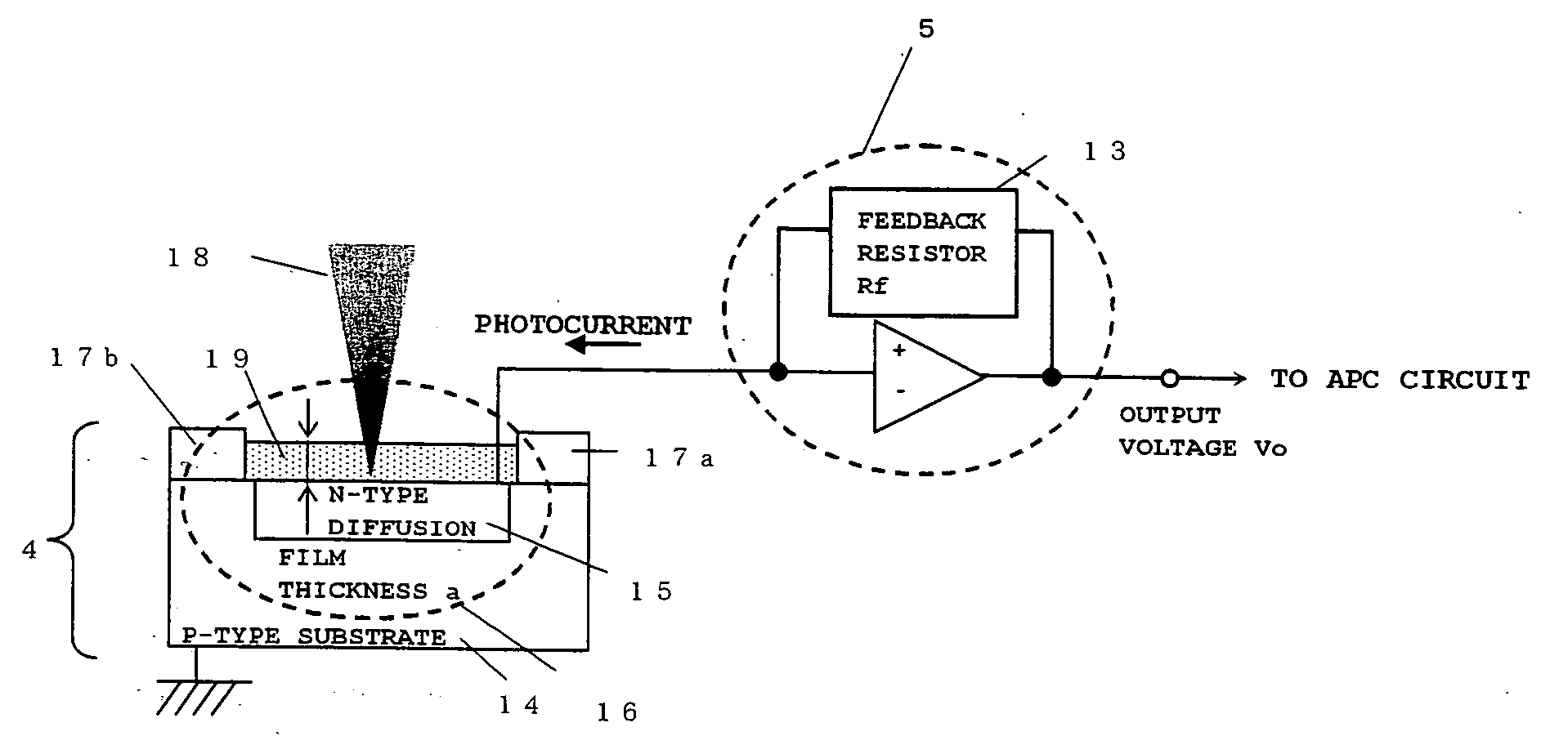
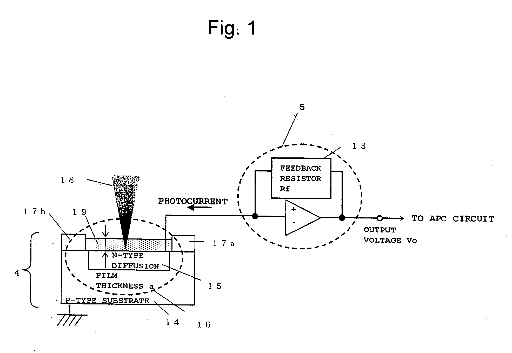
[0084]FIG. 1 is a diagram illustrating a configuration of a light receiving circuit according to a first embodiment of the present invention.

[0085] In FIG. 1, reference numeral 4 represents a photodiode for LD power monitoring; reference numeral 5, a photocurrent / voltage conversion amplifier (I-V amplifier) for LD power monitoring; reference numeral 13, a feedback resistor; reference numeral 14, an p-type semiconductor substrate; reference numeral 15, a n-type diffused region; reference numeral 16, a light receiving section; reference numerals 17a and 17b, substrate protective films; reference numeral 18, an incident light to the photodiode 4 for LD power monitoring; and reference numeral 19, a light receiving section protective film.

[0086] It should be noted that the p-type semiconductor substrate 14 and the n-type diffused region 15 may be a combination of a n-type substrate and an p-type diffused region, while a structure of the light receiving section 16 is not limited to that...

second embodiment

[0116]FIGS. 4A through 4C are diagrams illustrating configurations of the light receiving circuit according to a second embodiment of the present invention, wherein FIG. 4A shows the circuit without the protective film on the light receiving section; FIG. 4B, the circuit with the protective film on the light receiving circuit; and FIG. 4C, the circuit having the configuration of FIG. 4A with a light transmitting member coated on a glass plate.

[0117] In FIGS. 4A through 4C, reference numeral 20 represents the light transmitting member formed by a light transmitting material, and reference numeral 21 represents a glass substrate. For the other elements common with those in FIG. 1, the same reference numerals with FIG. 1 are provided and the description thereof will be omitted.

[0118] According to the present embodiment, it is characterized in that the light transmitting member 20 is disposed above the light receiving section 16. The incident light 18 enters into the light receiving s...

third embodiment

[0133]FIG. 6 is a diagram illustrating a configuration of the light receiving circuit according to a third embodiment of the present invention.

[0134] In FIG. 6, reference numeral 22 represents an area for forming an I-V amplifier, and reference numeral 23 represents a package. For the other elements common with those in FIGS. 1 and 4, the same reference numerals with FIGS. 1 and 4A through 4C are provided and the description thereof will be omitted.

[0135] The area for forming the I-V amplifier 22 is an area for forming the photocurrent / voltage conversion amplifier 5 (I-V amplifier) for LD power monitoring on the p-type semiconductor substrate 14, and is characterized in that the light receiving section 16 and the I-V amplifier 5 are formed on the same semiconductor substrate 14.

[0136] Moreover, the package 23 is provided for protecting the p-type semiconductor substrate 14 from a mechanical damage or the like, wherein the light transmitting member 20 is disposed on top of the pac...


PUM


Abstract

There is provided a light receiving circuit capable of preventing an output variation of the light receiving circuit due to a change in ambient temperature with a simple configuration.
The light receiving circuit is provided with a photodiode 4 for LD power monitoring and an I-V amplifier 5 connected with a feedback resistor 13, wherein a light receiving section 16 of the photodiode 4 is covered with a protective film 19. Temperature dependences between a light transmittance of the protective film 19 in accordance-with a shift of a wavelength of a laser beam due to a change in ambient temperature, and a resistance value of the feedback resistor 13 are set in such a way that they may be mutually compensated and an output voltage from the light receiving circuit may be constant for a temperature change.

Description

BACKGROUND OF THE INVENTION [0001] 1. Field of the Invention [0002] The present invention relates to a light receiving circuit, a semiconductor laser device, and an optical pickup device used for an optical information processing, an optical measurement, an optical communication, or an optical recording disk or the like. [0003] 2. Background Art [0004] In recent years, as a high-capacity information storage medium used for personal computers or recording a TV broadcast, an optical disk medium to which information can directly written, a so-called recording type optical disk medium has been popularized. The exemplary recording type optical disks include a CD-R and a DVD-R as write-once medium, and a CD-RW, a DVD-RW, and a DVD-RAM as repeatedly erasable / recordable medium. [0005]FIG. 7 is a schematic diagram of an optical pickup device according to the conventional art, wherein FIG. 7A shows an overall configuration and FIG. 7B shows a configuration of a light receiving circuit 100 for...

Claims


Application Information

Patent Timeline
IPC IPC(8): H01S3/13
CPCH01S5/0683H01S5/0264H04M1/0237
Inventor SHIMIZU, YUZOYASUKAWA, HISATADAHAMAGUCHI, SHINICHIIMAIZUMI, KENJIMIYAMOTO, SHINICHIKUROIWA, YOSUKE
Owner PANASONIC CORP
Why Eureka
Try Eureka