Apparatus and method for hanging a door

a technology for hanging doors and accessories, applied in the field of accessories and methods for hanging doors, can solve the problems of insufficient stability of prior systems for repeated use in both commercial and consumer applications, inability to meet the requirements of use,

Active Publication Date: 2008-09-09
NOMIS LLC
View PDF35 Cites 11 Cited by
  • Summary
  • Abstract
  • Description
  • Claims
  • Application Information

AI Technical Summary

Benefits of technology

[0007]The invention provides an improved apparatus and / or method for hanging a door in an associated door frame, through use of one or more templates and / or guide devices including elements or features providing significant advantage over prior devices systems, and methods for hanging doors.
[0019]The invention may take the form of an apparatus for hanging a door, having a face and an edge of the door, in an associated door frame, having a face and an edge of the door frame. Such an apparatus may include a template base, a first template, and a second template. The template base may have a mounting surface adapted for alternatively engaging the edge of the door when the template base is mounted on the door, and the face of the frame when the template base is mounted on the door frame. The first template may be adapted for mounting on the template base, for guiding a tool engaging the edge of the door, when the template base is mounted on the edge of the door, and for guiding a tool engaging the face of the door, when the template base is mounted on the face of the door frame. The second template may extend substantially perpendicularly from the template base, for guiding a tool engaging the face of the door, when the template base is engaging the edge of the door. At least one of the first or second templates may include a slot therein, for receiving the hooked end of a tape measure, to thereby facilitate positioning the template base.
[0024]First and second templates, according to the invention, may include openings therein for guiding tools forming intersecting first holes in the door edge and door face respectively, for installation of a lock set, with the second template also including an alignment opening extending therethrough, for marking a first vertical location of the apparatus on the door and door frame. An apparatus, according to the invention, may further include a dead bolt lock location guide, for facilitating marking of a desired vertical spacing for the dead bolt lock relative to the alignment opening in the second template. The dead bolt lock location guide may include indicia for marking two or more desired vertical spacings for the dead bolt lock relative to the alignment opening in the second template. The dead bolt lock location guide may be detachable from the template base and first and second templates, in an apparatus according to the invention.

Problems solved by technology

In general, prior devices and methods for providing mortises in a door and its associated frame have not been satisfactory, however.
Some prior systems are not sturdy enough for repeated use in both commercial and consumer applications.
Although such an approach is workable, in theory, experience has shown that the provisions for attaching the inserts into the template base, in prior devices, is overly complex and / or often does not result in a secure enough connection to preclude loosening the parts in service, or over time, which then leads to unacceptable inaccuracy in the position and / or shape of the mortises and holes formed by the prior devices.
Some prior devices for installing hinges and lock-sets in doors, while providing an acceptable required degree of accuracy, are too complex in their construction, and / or undesirably expensive, particularly for use by a home owner by individuals not regularly occupied with the installation of doors.

Method used


Image

  • Apparatus and method for hanging a door
  • Apparatus and method for hanging a door
  • Apparatus and method for hanging a door

Examples


Embodiment Construction

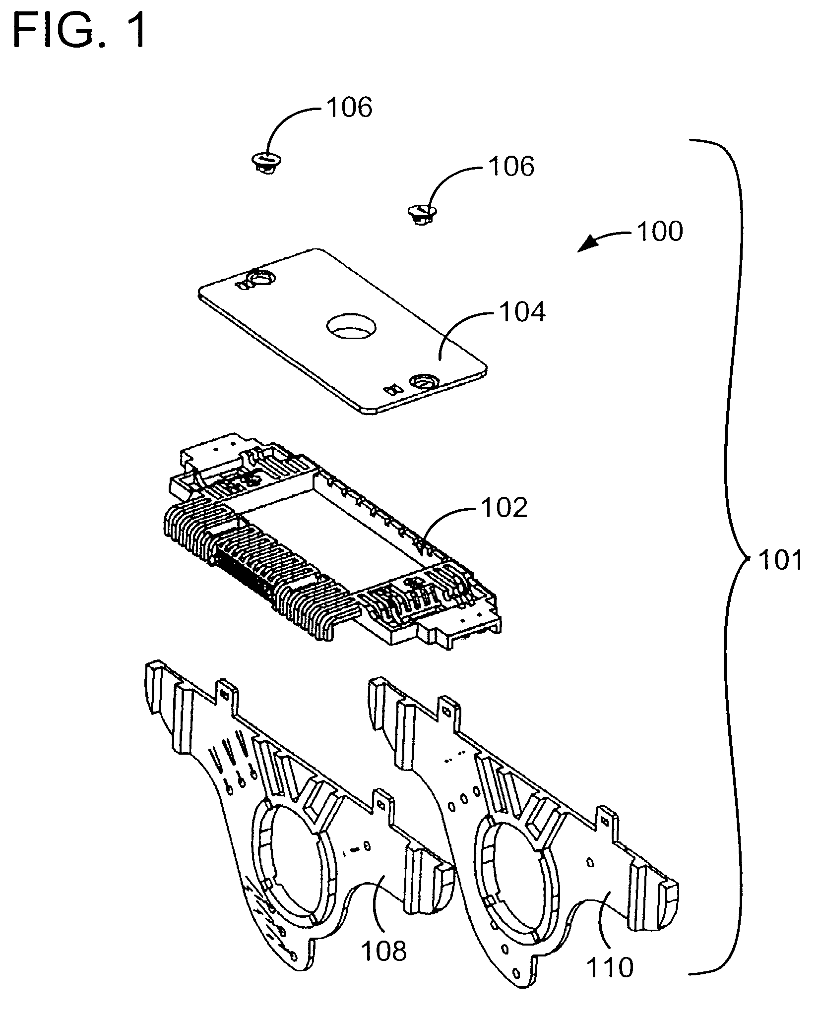
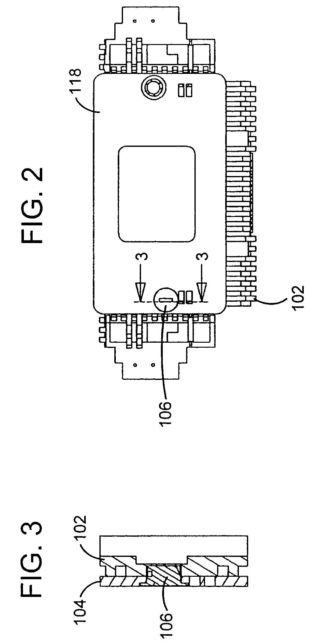
[0033]FIG. 1 illustrates a first exemplary embodiment of an apparatus 100, according to the invention, including a template base 102, a template insert 104, turn-lock fasteners 106, and door lock hole templates 108, 110. The template insert 104 is attached to the template base 102, in the exemplary embodiment, by the turn-lock fasteners 106 in the manner illustrated in FIGS. 2 and 3. The first and second door lock templates 108, 110 are also attached to the template base 102, with slide lock fasteners, in the manner described in more detail below, or any other appropriate manner, to provide a structure for guiding a drill and hole saw to form intersecting holes along one edge of a door for insertion and passage therethrough of a lock-set (not shown).

[0034]As shown in FIG. 4, the exemplary embodiment of the apparatus 100 may further include an adjustable length leg 112, adapted for attachment to a groove in the template base 102 of the lock-set template 101, so that the apparatus 100...


PUM


Abstract

An apparatus and / or method for hanging a door in an associated frame are provided, through the use of one or more templates and / or guide devices including elements and features which facilitate proper positioning of mortises and / or holes in the door and door frame, for hinge and lock-set hardware.

Description

CROSS-REFERENCE TO RELATED PATENT APPLICATIONS[0001]This patent application claims the benefit of U.S. Provisional Patent Application Nos. 60 / 686,657 filed on Jun. 1, 2005 and 60 / 788,142 filed on Mar. 31, 2006, the disclosures of which are incorporated herein in their entirety by reference.FIELD OF THE INVENTION[0002]The invention relates to an apparatus and method for hanging doors, and more specifically to apparatus and method for providing mortises and / or holes in a door and in a frame supporting a door, for hinge and lock-set hardware.BACKGROUND OF THE INVENTION[0003]In the past, many types of devices have been provided for positioning and guiding routers, drills, or other tools utilized for forming mortises along the edge of a door frame to receive the door hinges, and hardware associated with the lock-set, such as a strike plate. Various types of prior devises have also been provided for positioning and guiding drill bits and tools, such as hole saws, for use in making interse...

Claims


Application Information

Patent Timeline
Patent Type & Authority Patents(United States)
IPC IPC(8): E04F21/00E05B17/06
CPCB23B47/287E05D11/0009E05B17/06E05Y2900/132
Inventor ADKINS, EDWARD D.KOZINA, DAMIAN A.
Owner NOMIS LLC
Why Eureka
Try Eureka