Shielded electric connector and cable assembly and method for making same

a shielded electric connector and cable assembly technology, applied in the direction of electrical equipment, connections, connections effected by permanent deformation, etc., can solve the problems of compromising the shielding efficiency of the arrangement, high cost of the shielded electric cable assembly disclosed in the sakurai et al. patent, and difficult to manufacture primarily

Active Publication Date: 2008-09-09
APTIV TECH LTD
View PDF3 Cites 50 Cited by
  • Summary
  • Abstract
  • Description
  • Claims
  • Application Information

AI Technical Summary

Benefits of technology

[0008]In one aspect the invention provides a shielded electric connector that includes an outer shielding terminal that has an open bay for receiving a bared core end of a shielded electric cable on an anvil in the open bay that supports core crimp wings of an inner terminal. The anvil is part of an insulator in the outer terminal that includes a crimp tool for crimping the core crimp wings of the inner terminal to the bared core end of the shielded electric cable. The open bay may include at least one side wall flap for assisting in the crimping operation and enclosing the bay around the core crimp wings.

Problems solved by technology

The shielded electric cable assembly disclosed in the Sakurai et al. patent is expensive and difficult to manufacture primarily because it involves the fabrication of two separate sub-assemblies that must be attached to the electric cable at different times, namely an inner terminal sub-assembly that is attached to the cable and an outer or shielding terminal sub-assembly which must be joined to the inner sub-assembly and then attached to the cable.
While the U.S. Pat. No. 7,160,150 B2 does disclose a shielded electric cable assembly that can be fabricated in an easier manner, the Annequin shielded cable assembly nevertheless has a draw back in that the shielded electric cable assembly has a large opening in the shielding terminal that exposes the core crimp wings of the inner terminal thus compromising the shielding efficiency of the arrangement.

Method used


Image

  • Shielded electric connector and cable assembly and method for making same
  • Shielded electric connector and cable assembly and method for making same
  • Shielded electric connector and cable assembly and method for making same

Examples


Embodiment Construction

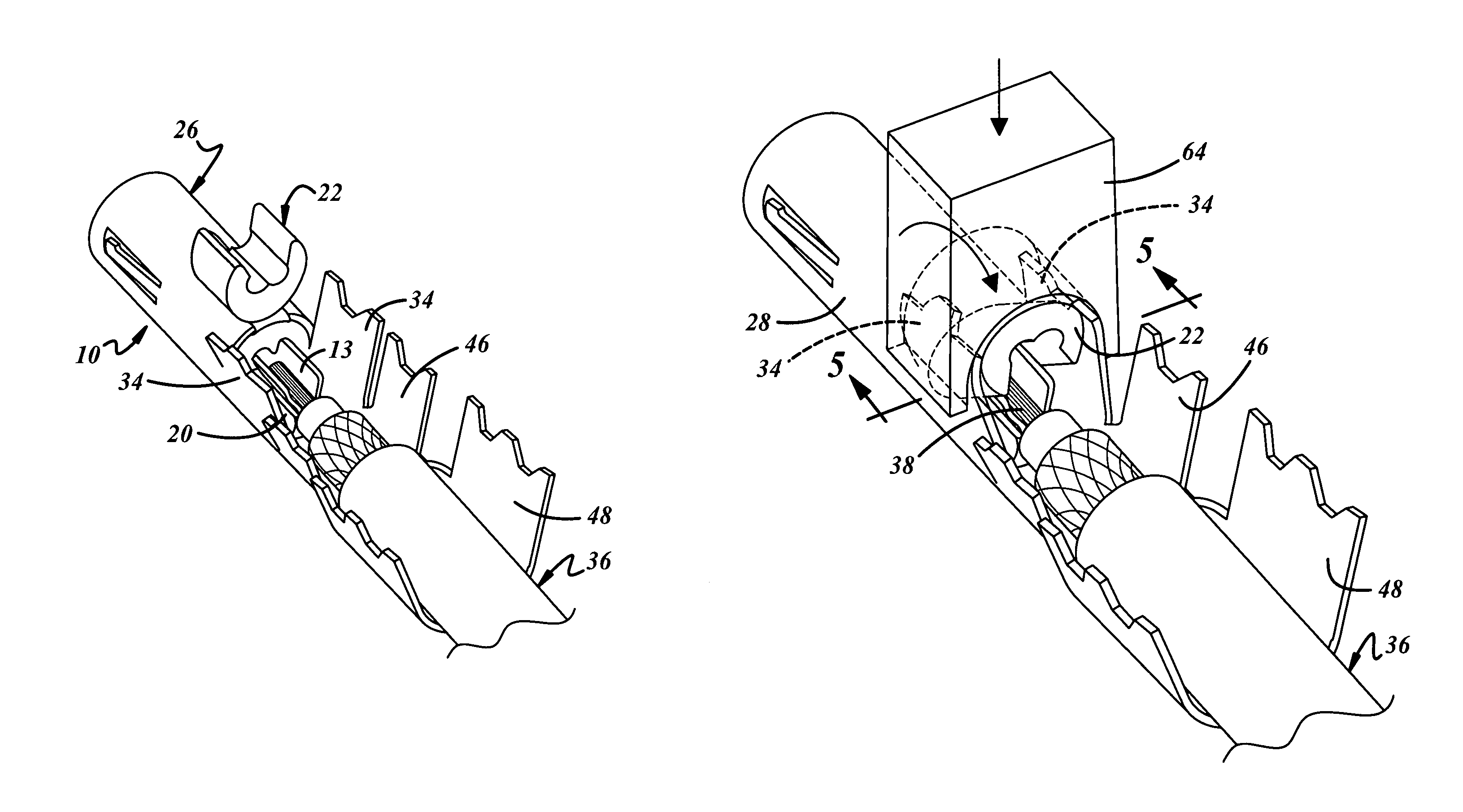
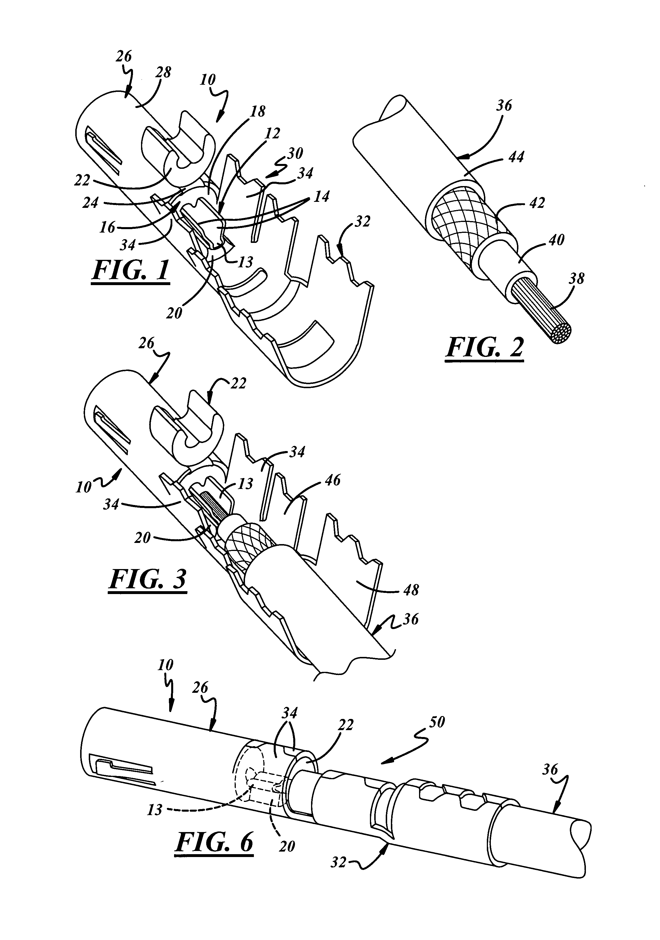
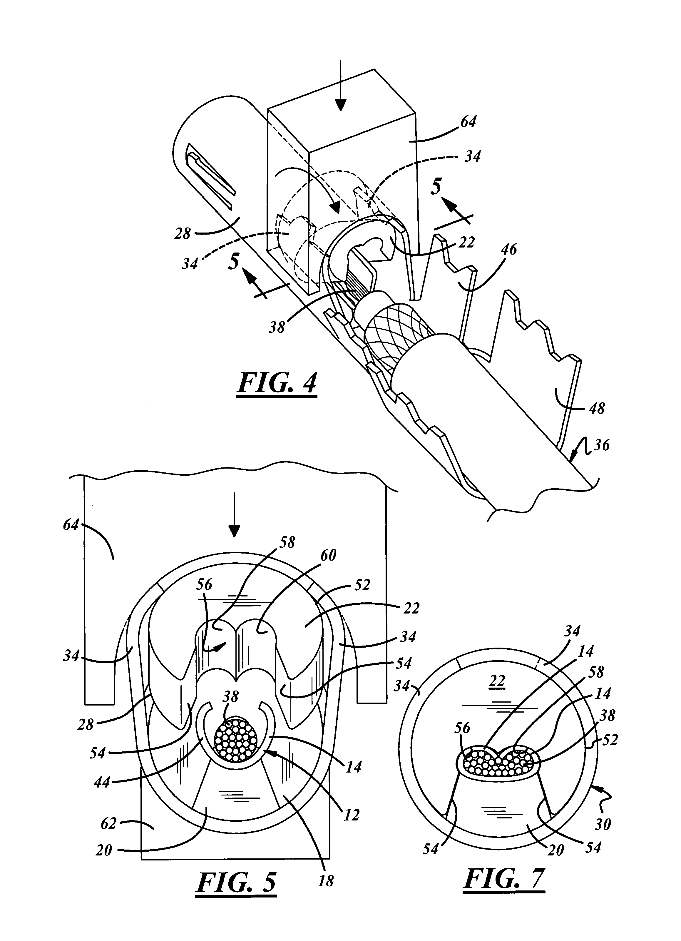
[0024]Referring now to the drawing, FIG. 1 shows a shielded electric connector 10 comprising an inner terminal 12 having a forward contact portion (not shown) and a rearward attachment portion 13 that includes core crimp wings 14. The shielded electric connector 10 further comprises an insulator 16 having a forward housing 18 for the forward contact portion of the inner terminal 12 and a rearward anvil 20 that that projects from a rearward end of the housing 18 in a fixed manner. Insulator 16 has a crimp tool 22 that is integrally attached to the rearward end of the housing 18 by a flexible hinge strap 24.

[0025]The forward contact portion of the inner terminal 12 is disposed in the forward housing 18 of the insulator 16 with the rearward attachment portion 13 of the inner terminal 12 supported on the projecting rearward anvil 20 of the insulator 16 as best shown in FIG. 1. The shielded electric connector 10 also includes an outer shielding terminal 26 that has a forward housing 28, ...


PUM


Abstract

A shielded electric cable assembly comprises a shielded electric cable and a shielded electric connector that has an inner terminal, an insulator and an outer shielding terminal. The inner terminal has an attachment portion that is supported on a projecting anvil of the insulator that is disposed in an intermediate bay of the outer shielding terminal. The bay has an opening for a crimp tool that crimps the attachment portion of the inner terminal onto an exposed end of a conductive core of the shielded electric cable. The intermediate bay is closed by side wall flaps of the intermediate bay or by a closure shell. The crimp tool that may be part of the insulator.

Description

BACKGROUND OF THE INVENTION[0001]This invention relates generally to a shielded electric connector a shielded electric cable assembly and a method of making a shielded electric cable assembly.[0002]A shielded electric cable assembly generally comprises a shielded electric cable, that has a conductor core that is surrounded by an inner insulation jacket, an intermediate conductive layer, and an outer insulation jacket. An inner terminal is attached to the conductor core as part of the assembly for making an electric connection to a mating terminal and a shield terminal is attached to the conductive layer. The conductive layer and shield terminal shield any electronic devices in the vicinity of the shielded electric cable assembly from electromagnetic interference (generally designated EMI) caused by electric current flowing through the conductive core and inner terminal.[0003]A common shielded electric cable has an intermediate conductive layer in the form of a metallic braid that is...

Claims


Application Information

Patent Timeline
Patent Type & Authority Patents(United States)
IPC IPC(8): H01R9/05
CPCH01R9/0518
Inventor MUSICK, STEVEN A.MLAKAR, FREDERICK E.ESENWEIN, FREDERICK D.
Owner APTIV TECH LTD
Why Eureka
Try Eureka