Multi-band monopole antennas for mobile communications devices

a technology of mobile communications and antennas, applied in the structural form of antennas, antenna supports/mountings, radiating elements, etc., can solve the problems of inverted-f antennas, often subject to electromagnetic interference, and bandwidth-limited antennas

Inactive Publication Date: 2008-09-09
FRACTUS
View PDF105 Cites 67 Cited by
  • Summary
  • Abstract
  • Description
  • Claims
  • Application Information

AI Technical Summary

Problems solved by technology

When mounted inside a mobile communications device, an antenna is often subject to problematic amounts of electromagnetic interference from other metallic objects within the mobile communications device, particularly from the ground plane.
Inverted-F antennas, however, are typically bandwidth-limited, and thus may not be well suited for bandwidth intensive applications.

Method used


Image

  • Multi-band monopole antennas for mobile communications devices
  • Multi-band monopole antennas for mobile communications devices
  • Multi-band monopole antennas for mobile communications devices

Examples


Embodiment Construction

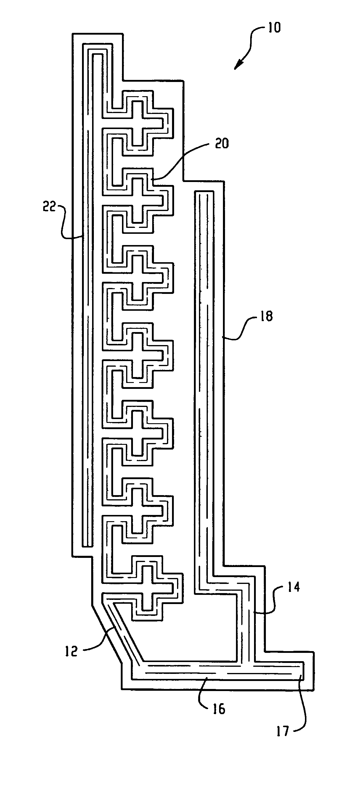
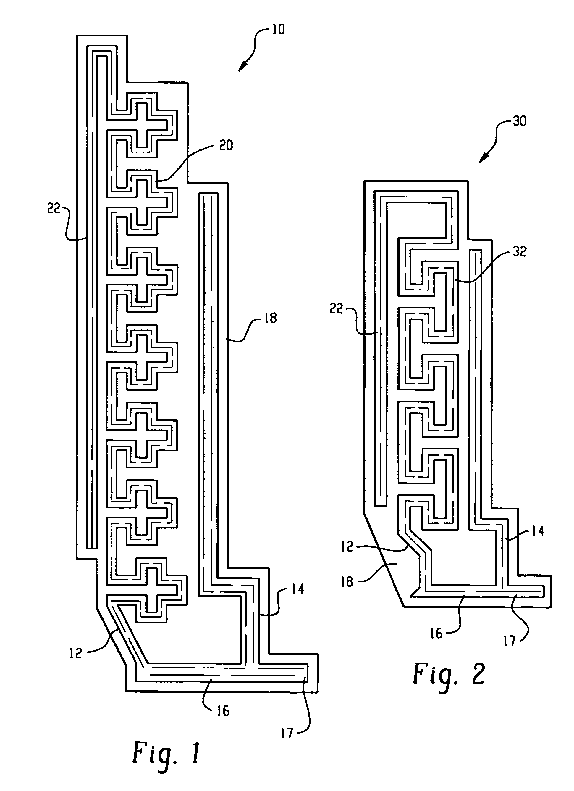
[0026]Referring now to the drawing figures, FIG. 1 is a top view of an exemplary multi-band monopole antenna 10 for a mobile communications device. The multi-band monopole antenna 10 includes a first radiating arm 12 and a second radiating arm 14 that are both coupled to a feeding port 17 through a common conductor 16. The antenna 10 also includes a substrate material 18 on which the antenna structure 12, 14, 16 is fabricated, such as a dielectric substrate, a flex-film substrate, or some other type of suitable substrate material. The antenna structure 12, 14, 16 is preferably patterned from a conductive material, such as a metallic thick-film paste that is printed and cured on the substrate material 18, but may alternatively be fabricated using other known fabrication techniques.

[0027]The first radiating arm 12 includes a meandering section 20 and an extended section 22. The meandering section 20 is coupled to and extends away from the common conductor 16. The extended section 22 i...


PUM


Abstract

Antennas for use in mobile communication devices are disclosed. The antennas disclosed can include a substrate with a base, a top, a front side and a back side; a first conductor can be located on the first side of the antenna substrate; and a second conductor can be located on the second side of the antenna substrate. The conductors can have single or multiple branches. If a conductor is a single branch it can, for example, be a spiral conductor or a conducting plate. If a conductor has multiple branches, each branch can be set up to receive a different frequency band. A conductor with multiple branches can have a linear branch and a space-filling or grid dimension branch. A conducting plate can act as a parasitic reflector plane to tune or partially tune the resonant frequency of another conductor. The first and second conductors can be electrically connected.

Description

[0001]This patent application is a national stage entry of PCT / EP05 / 00880 filed on Jan. 28, 2005,which is a continuation-in-part of PCT / EP02 / 14706 filed Dec. 22, 2002. PCT / EP05 / 00880 claims priority from provisional application 60 / 540,450 filed on Jan. 30,2004.INTRODUCTION[0002]This invention relates generally to the field of multi-band monopole internal and external antennas. More specifically, multi-band monopole antennas are provided that are particularly well-suited for use in mobile communications devices, such as Personal Digital Assistants, cellular telephones, and pagers.BACKGROUND[0003]Multi-band antenna structures for use in a mobile communications device are known in this art. For example, one type of antenna structure that is commonly utilized as an internally-mounted antenna for a mobile communication device is known as an “inverted-F” antenna. When mounted inside a mobile communications device, an antenna is often subject to problematic amounts of electromagnetic inter...

Claims


Application Information

Patent Timeline
Patent Type & Authority Patents(United States)
IPC IPC(8): H01Q1/38H01Q1/24H01Q1/36H01Q5/371H01Q9/27H01Q9/30H01Q9/42H01Q21/30
CPCH01Q1/243H01Q1/38H01Q9/30H01Q9/40H01Q5/371H01Q21/30H01Q5/0027H01Q5/307H01Q9/42
Inventor PROS, JAUME ANGUERABALIARDA, CARLES PUENTE
Owner FRACTUS
Why Eureka
Try Eureka