Passive electrode blanketing in a fuel cell

a fuel cell and passive electrode technology, applied in the field of fuel cells, can solve the problems of small amounts of hydrogen fuel and oxidant remaining inside, increased wear and degradation rate of some components of pem fuel cells, and known combustibility during shutdown and restarting processes

Active Publication Date: 2008-09-16
HYDROGENICS CORP
View PDF31 Cites 27 Cited by
  • Summary
  • Abstract
  • Description
  • Claims
  • Application Information

AI Technical Summary

Benefits of technology

[0009]In some embodiments the reactant reservoir is sized such that a near stoichiometric amount of the first reactant stored in the reactant reservoir to electrochemically consume the amount of the second reactant remaining in the fuel cell module during the shutdown process so as to deter other undesired reactions from occurring and cause respective pressure drops within the fuel cell module as the remaining amounts of the first and second reactants are electrochemically consumed.
[0012]According to aspects of another embodiment of the invention there is provided a process for shutting down a fuel cell, the fuel cell including a first electrode, a second electrode and an electrolyte membrane arranged between the first and second electrodes, wherein during normal operation the first electrode is provided with a first reactant and the second electrode is provided with a first mixture containing a second reactant and a non-reactive agent, the process comprising: stopping an inflow of the first reactant into the first electrode; cutting-off power to supporting balance of plant elements drawing current through a parasitic load connectable across the first and second electrodes; providing a pre-stored near stoichiometric amount of a first reactant for the electrochemical consumption of a remaining amount of a second reactant; and, permitting a delayed inflow of an amount of the first mixture into the second electrode; wherein the near stoichiometric amount of the first reactant electrochemically reacts with the remaining amount of the second reactant, thereby leaving a second mixture that substantially comprises the non-reactive agent.

Problems solved by technology

A number of factors cause other undesired reactions to occur that increase the rate of wear and degradation experienced by some components of a PEM fuel cell.
For example, small amounts of hydrogen fuel and oxidant remaining inside a PEM fuel cell, after respective supplies of these reactants are closed off, are known to combust during shutdown and restarting processes.
Combustion within a PEM fuel cell causes the deterioration of various components including the electrolyte membrane and catalyst layers deposited on the electrodes.
The cumulative deterioration of various components significantly reduces the efficiency of the PEM fuel cell and may lead to failure of the PEM fuel cell.
Another undesired reaction that may occur is the electrochemical corrosion of at least one catalyst layer within a PEM fuel cell.
This further deteriorates the performance of a PEM fuel cell.

Method used


Image

  • Passive electrode blanketing in a fuel cell
  • Passive electrode blanketing in a fuel cell
  • Passive electrode blanketing in a fuel cell

Examples


Embodiment Construction

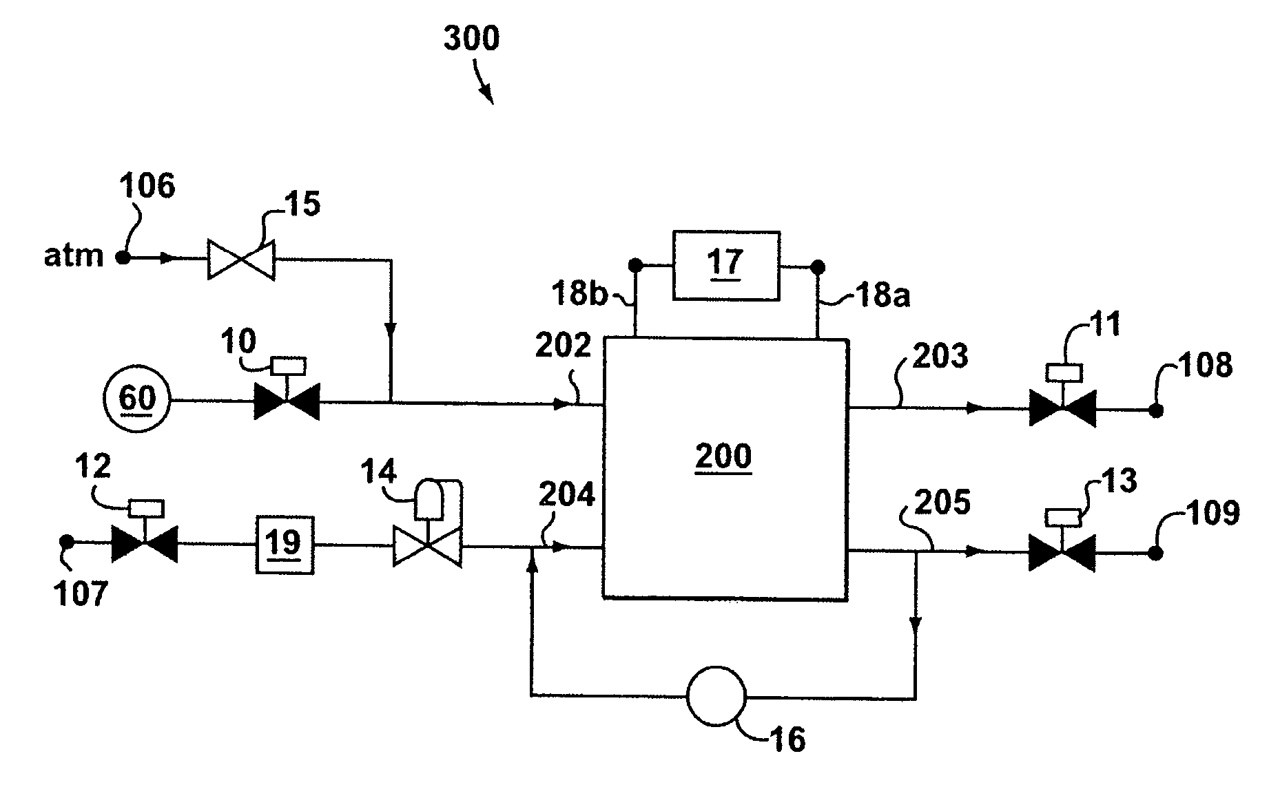
[0021]A fuel cell module is typically made up of a number of fuel cells connected in series to form a fuel cell stack. The fuel cell module also includes a suitable combination of associated structural elements, mechanical systems, hardware, firmware and software that is employed to support the function and operation of the fuel cell module. Such items include, without limitation, piping, sensors, regulators, current collectors, seals and insulators.

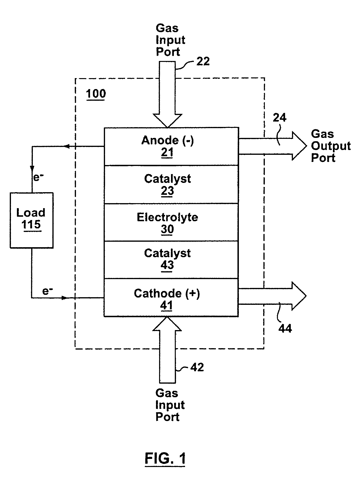
[0022]Referring to FIG. 1, shown is a simplified schematic diagram of a Proton Exchange Membrane (PEM) fuel cell module, simply referred to as fuel cell module 100 hereinafter, that is described herein to illustrate some general considerations relating to the operation of fuel cell modules. It is to be understood that the present invention is applicable to various configurations of fuel cell modules that each include one or more fuel cells.

[0023]There are a number of different fuel cell technologies, and in general, this invention is exp...


PUM

PropertyMeasurementUnit
pressureaaaaaaaaaa
pressureaaaaaaaaaa
pressureaaaaaaaaaa

Abstract

A fuel cell module is provided having a fuel cell stack, a parasitic load connectable across the electrodes, and a reactant reservoir for storing an amount of a first reactant such as hydrogen. When the fuel cell module is shutdown, the stored amount of the first reactant can be drawn to react with an amount of a second reactant (e.g., oxygen in air) remaining in the stack to electrochemically consume the first and second reactants, thereby leaving a mixture that substantially comprises a non-reactive agent (e.g., nitrogen), thereby passively blanketing the electrodes. The parasitic load limits the voltage of the fuel cell stack and induces the electrochemical consumption of the first and second reactants remaining in the stack during shutdown. A pressure gradient between the electrodes and an optional check valve may allow for movement of the non-reactive agent between electrodes. A process related to said fuel cell module is also provided.

Description

PRIORITY CLAIM[0001]This application claims the benefit of U.S. Provisional Application No. 60 / 482,010 (filed on Jun. 25, 2003) and the benefit of U.S. Provisional Application No. 60 / 495,091 (filed on Aug. 15, 2003). Accordingly, the entire contents of both U.S. Provisional Application Nos. 60 / 482,010 and 60 / 495,091 are hereby incorporated by reference.FIELD OF THE INVENTION[0002]The invention relates to fuel cells, and, in particular to reducing the rate of wear and degradation experienced by some components of a fuel cell during shutdown and restarting periods.BACKGROUND OF THE INVENTION[0003]A fuel cell converts chemical energy stored in a fuel into a useful form of energy, such as for example, electricity. One example of a particular type of fuel cell is a Proton Exchange Membrane (PEM) fuel cell that is operable to produce electricity.[0004]A typical PEM fuel cell includes an electrolyte membrane arranged between an anode electrode and a cathode electrode. Hydrogen fuel is supp...

Claims


Application Information

Patent Timeline
Patent Type & Authority Patents(United States)
IPC IPC(8): H01M8/04H01M8/06
CPCH01M8/04089H01M8/04201H01M8/04223H01M8/04425H01M8/04753H01M8/0662H01M8/04231H01M8/04022Y02E60/50Y02E60/523H01M8/04303H01M8/04228
Inventor JOOS, NATHANIEL IAN
Owner HYDROGENICS CORP
Why Eureka
Try Eureka