Card connector

a card connector and connector technology, applied in the direction of coupling device connection, instruments, conveying record carriers, etc., can solve the problems of difficult removal of memory cards from the tray, difficult inserting and removing memory cards into and out of the connector, etc., and achieve the effect of convenient removal of memory cards and compact construction

Inactive Publication Date: 2008-09-23
DDK LTD
View PDF13 Cites 40 Cited by
  • Summary
  • Abstract
  • Description
  • Claims
  • Application Information

AI Technical Summary

Benefits of technology

[0012]In view of these problems of the prior art, the invention has an object to provided a card connector which is simple, and lighter and more compact in construction, and is easy to remove a memory card.
[0018](1) In a card connector 10 into and from which a memory card 60 is detachably inserted and removed, including contacts 14 each adapted to contact a connection portion of the memory card 60, and a housing 12 for arranging and holding said contacts 14 and having an inserting opening 22 for inserting the memory card 60, according to the invention said housing 12 comprises two side walls 24, a rear wall 26, and a lower wall 28 contiguous to these side and rear walls 24 and 26 to form said inserting opening 22 for said memory card by said two side walls 24, said rear wall 26, and said lower wall 28, and further a shell 16 is arranged on the side of said housing 12 opposite from said lower wall 28, and an elastically deformable tray 18 is arranged on said lower wall 28 so as to be slidable with the aid of a tray restraining plate 20. According to the invention, therefore, it is possible to provide a lighter and more compact card connector, for example, having a thickness of less than 1.8 mm, and being capable of easily removing said memory card 60.
[0019]In the card connector 10 as claimed in claim 2, according to the invention said tray 18 is made of a metal having an elasticity in the form of a plate and comprises at one free end an operating portion 36 extending from the end face of said lower wall when said memory card has been worn so that said tray 18 is slidably moved by drawing said operating portion 36. Consequently, it is possible to provide a lighter and more compact card connector and being capable of easily removing said memory card 60 because said tray 18 is made of a metal having an elasticity.
[0021]In the card connector 10 as claimed in claim 4, according to the invention said tray 18 is formed as a plate-shaped piece so that a space is provided below the lower surface of said memory card 60 when said tray 18 has been drawn from the housing. Accordingly, said memory card can be readily removed even with the lighter and more compact card connector.

Problems solved by technology

On the other hand, as the connector becomes lighter and more compact, it becomes difficult to insert and remove a memory card into and from the connector.
On the other hand, the card connector of the tray type as disclosed in the Patent Literature 2 has a problem that removal of a memory card from the tray would be difficult after the tray has been drawn from the connector.

Method used


Image

  • Card connector
  • Card connector
  • Card connector

Examples


Embodiment Construction

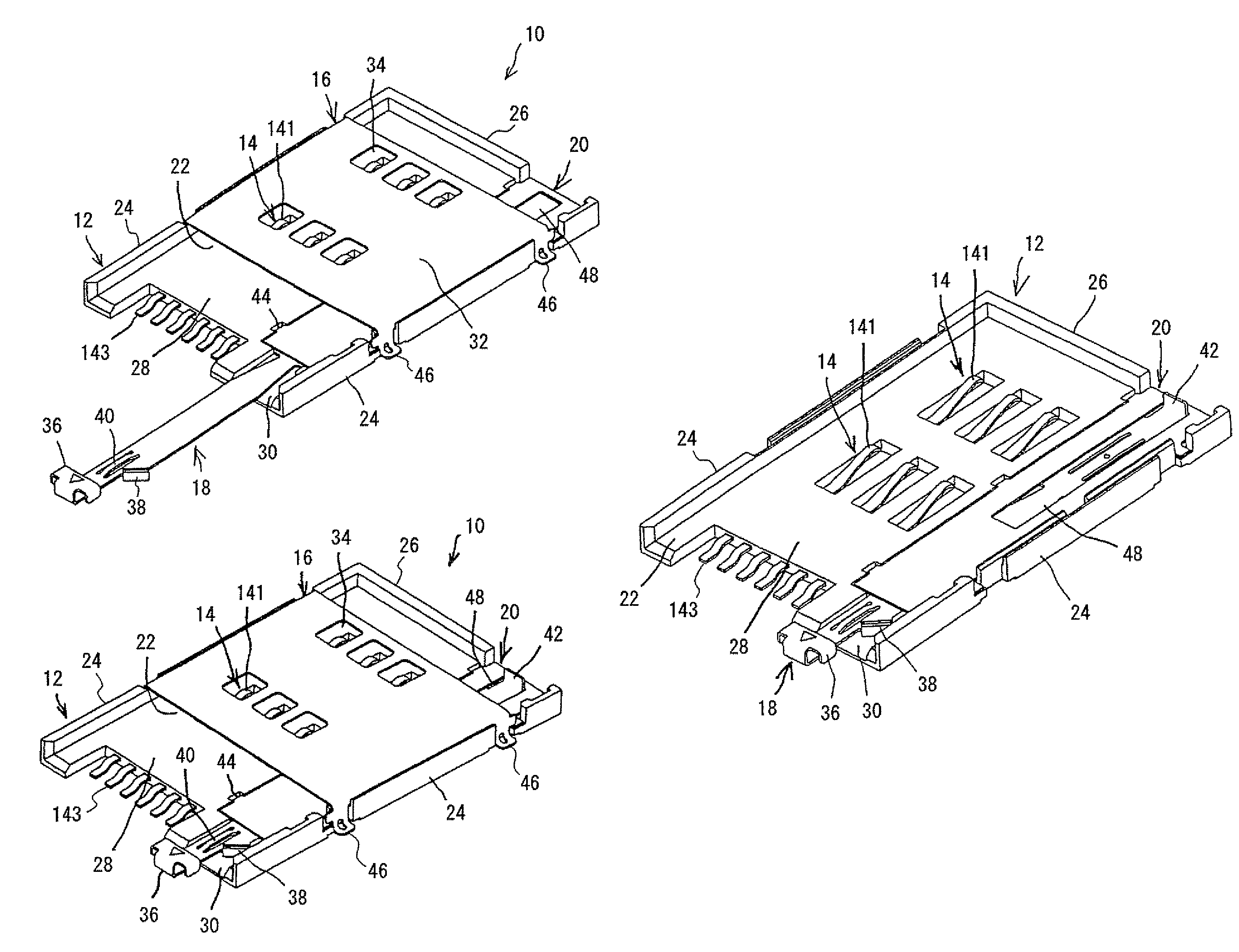
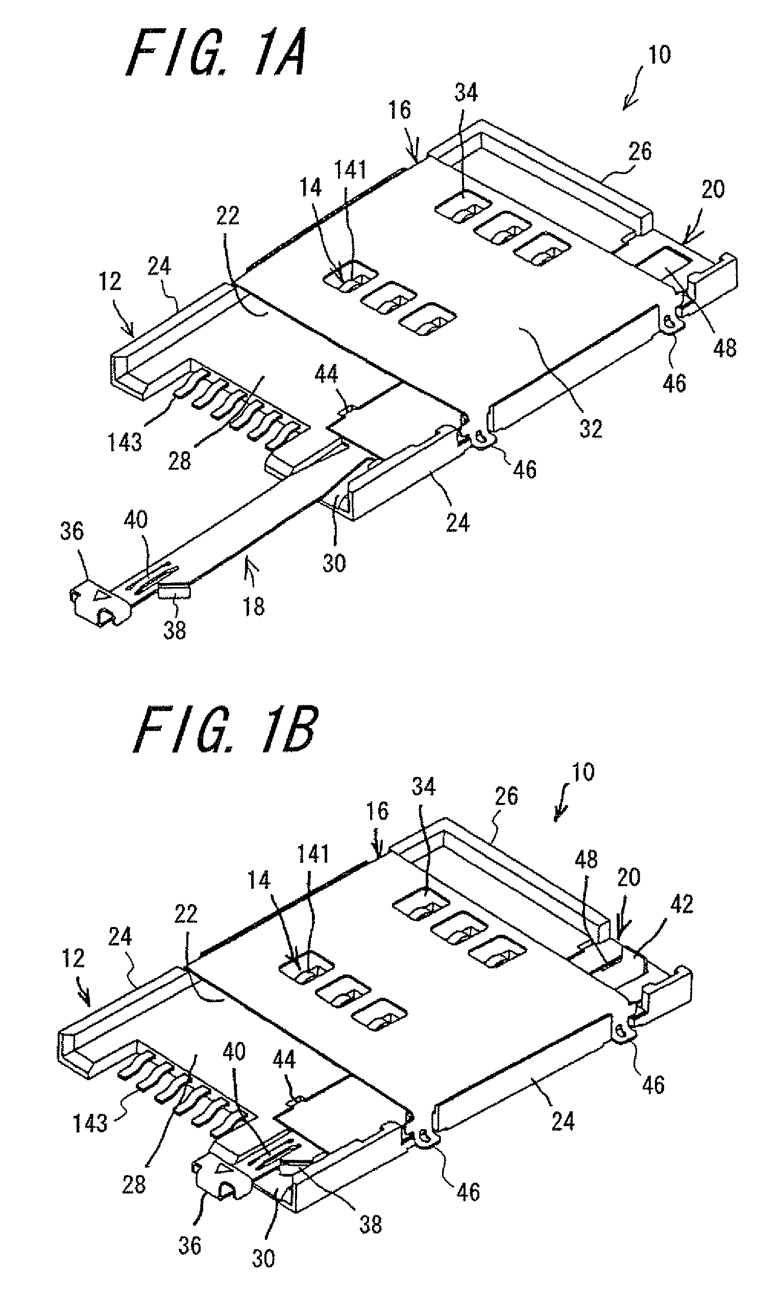
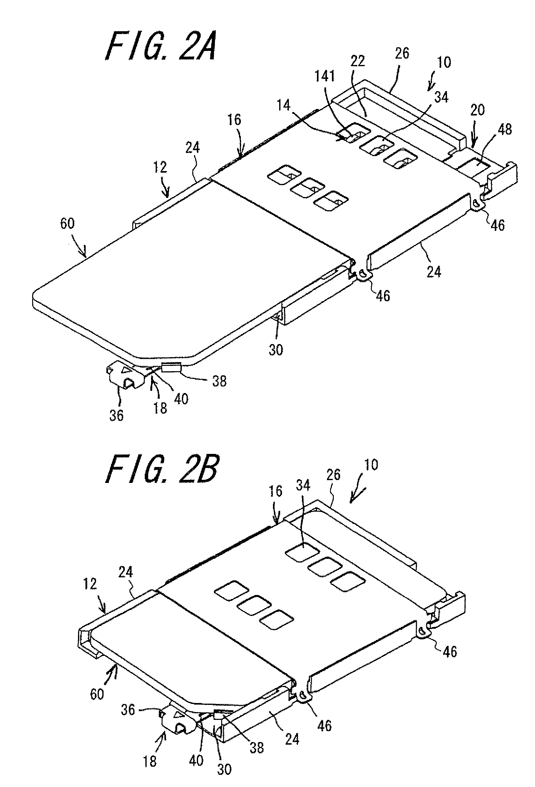
[0032]One embodiment of the card connector according to the invention will be explained with reference to FIG. 1A to 7. FIG. 1A is a perspective view of the card connector with a tray drawn, viewed from the fitting side, and FIG. 1B is a perspective view of the card connector with a tray completely inserted, viewed from the fitting side. FIG. 2A is a perspective view of the card connector with the tray drawn and a card worn on the tray, viewed from the fitting side, while FIG. 2B is a perspective view of the card connector with the card worn and the tray inserted, viewed from the fitting side. FIG. 3 is a perspective view of the tray, while FIG. 4 is a perspective view of a tray restraining plate. FIG. 5 is a perspective view of a housing with contacts held therein, and FIG. 6 is a perspective view of a shell. FIG. 7 is a perspective view of the card connector with the shell removed.

[0033]The card connector 10 of the one embodiment according to the invention mainly comprises the hou...


PUM


Abstract

A card connector into and from which a memory card is detachably inserted and removed, includes contacts each adapted to contact a connection portion of the memory card, and a housing for arranging and holding the contacts and having an inserting opening for inserting the memory card. The housing includes two side walls, a rear wall, and a lower wall contiguous to these side and rear walls to form the inserting opening for the memory card by these walls. A shell is arranged on the side of the housing opposite from the lower wall, and an elastically deformable tray is arranged on the lower wall so as to be slidable with the aid of a tray restraining plate. The card connector is miniaturized and lighter, more compact and simple in construction and is easy to remove a memory card.

Description

BACKGROUND OF THE INVENTION[0001]This invention relates to a card connector for use in a various electric and electronic appliances such as mobile phone, personal digital assistant (PDA), printers, card readers and the like for inputting and outputting signals into and from memory cards inserted into the card connector, and more particularly to a card connector having a structure for easily removing the memory card, while maintaining a reduced overall height of the card connector.[0002]In recent years, with the wide spread use of digital cameras and the like, memory cards having a large memory capacity and a compact shape have been used. A wide variety of memory cards have also been used depending upon characteristics and the like of appliances with which the memory cards are used, for example, SD card (Secure Digital memory card, registered trademark, referred to hereinafter just as “SD card”), Memory Stick card (registered trademark, referred to hereinafter just as “MS card”), Sma...

Claims


Application Information

Patent Timeline
Patent Type & Authority Patents(United States)
IPC IPC(8): H01R13/62
CPCG06K13/0831G06K7/0021
Inventor TAKEI, KAZUNORITAKAHASHI, HIROKAZUKIKUCHI, HITOSHI
Owner DDK LTD
Why Eureka
Try Eureka