Multi-length flexible image bundle

a fiberscope and bundle technology, applied in the field of fiberscopes, can solve the problems of high production cost, low process yield, brittle image fibers, etc., and achieve the effect of reducing production cost, reducing production cost, and reducing production cos

Inactive Publication Date: 2008-09-30
KARL STORZ ENDOVISION INC
View PDF14 Cites 6 Cited by
  • Summary
  • Abstract
  • Description
  • Claims
  • Application Information

AI Technical Summary

Problems solved by technology

One problem with image fiber bundle manufacturing techniques is the relatively high production cost and relatively low process yield.
Image fibers are brittle and susceptible to breaking during the manufacturing process.
Given the number of fibers in a bundle (1,000 to 50,000), the length of the bundle (from 100 mm to 3000 mm) and small size of a fiber (from 5 micrometers to 15 micrometers), it is very challenging to manufacture a fiber scope with no broken fibers.
Giving the probability of high scrap rates, keeping the manufacturing cost of fiberscopes down and delivering fiberscopes in a timely manner can be challenging.

Method used


Image

  • Multi-length flexible image bundle
  • Multi-length flexible image bundle
  • Multi-length flexible image bundle

Examples


Embodiment Construction

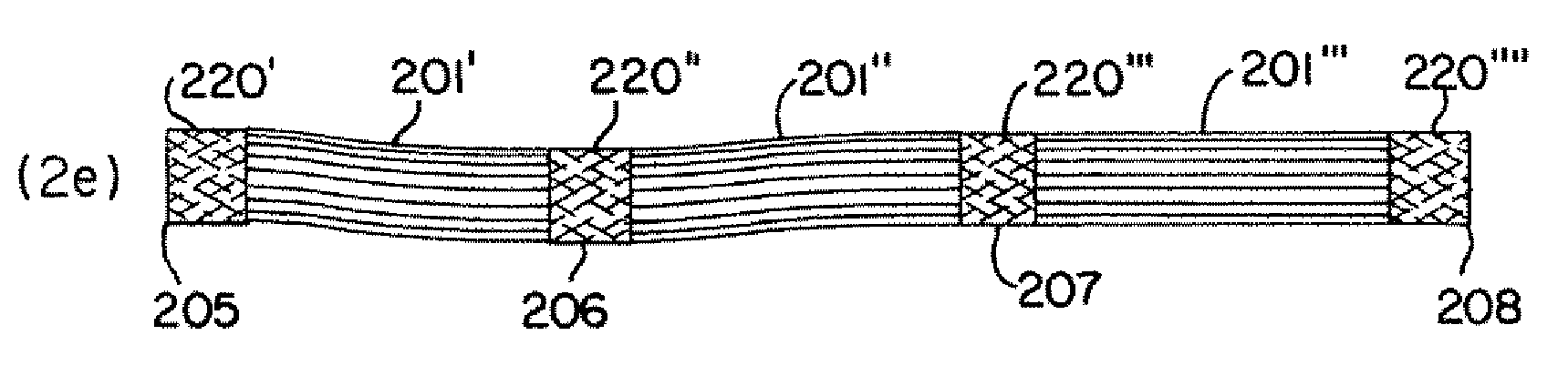
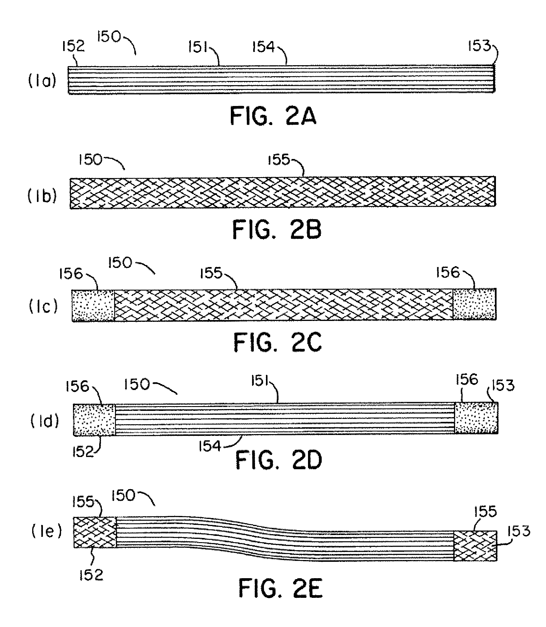
[0030]FIGS. 3A-3E and 4A-C depict a process of manufacturing image fiber bundle 200 for a plurality of fiber scopes of different lengths. At step 2(a), individual fibers 201 are brought together to form a bundle with a proximal end 202, a distal end 203 and a transition region 204. It is also possible to identify within fiber bundle 200 several points 205-208. The individual fibers 201 are coherently aligned at least at each of these points 205-208. As such, it is possible for the fibers to be coherently aligned at points 205-208 and not coherently aligned in the areas between these regions.

[0031]Each point 205-208 or summation of points can correspond to a useable fiberscope length, such as different standardized fiberscope lengths. Such standardized fiberscope lengths can come from industry standard lengths or length variations in a company's product line. The distance between points 205 and 208 forms Length (A) which corresponds to a fiberscope of the greatest length, such as 300...


PUM

PropertyMeasurementUnit
diameteraaaaaaaaaa
sizeaaaaaaaaaa
sizeaaaaaaaaaa

Abstract

A method for manufacturing an image fiber bundle that includes the steps of aligning a plurality of image fibers into a bundle, bonding the plurality of image fibers in at least three regions to form an image fiber bundle with a useable length and at least one useable sub-length, and inspecting the image fiber bundle for defective image fibers. The image fiber bundle includes flexible regions disposed between the bonded regions and the spacing of the bonded regions corresponds to a plurality of standardized lengths for fiberscopes.

Description

FIELD OF THE INVENTION[0001]This invention relates to fiberscopes, in particularly to methods for manufacturing the fiber optic bundles utilized in fiberscopes.BACKGROUND OF THE INVENTION[0002]In medical and industrial flexible fiberscopes, an image is transmitted using a bundle of coherently aligned optical fibers, which form a fiber bundle. The number of fibers in a fiber bundle varies from 1000 to 50,000 depending on the application and the size of the bundle. Each fiber, which can represent a pixel, transmits a small portion of the image, and the combination of the images from each fiber generates the whole image. To do so, coherent alignment of fibers in the fiber bundle is required in the distal and proximal ends of the bundle in order to correctly transmit the image from one end to other end. The distal end corresponds to the end where the image is located and the proximal end corresponds to the end where the image is observed.[0003]FIG. 1 is a depiction of a fiber bundle 100...

Claims


Application Information

Patent Timeline
Patent Type & Authority Patents(United States)
IPC IPC(8): G02B6/06C03B37/01
CPCG02B6/06
Inventor LAFOREST, MICHAEL F.KUCUK, AHMET
Owner KARL STORZ ENDOVISION INC
Why Eureka
Try Eureka