Method and apparatus for imaging of radiation sources

a radiation source and imaging technology, applied in the field of radiation imaging, can solve the problems of obscuring the signal of interest, exceedingly difficult to distinguish beta particles from the large gamma ray background, and noise artefacts

Active Publication Date: 2017-03-07
LIGHTPOINT SURGICAL LTD
View PDF11 Cites 2 Cited by
  • Summary
  • Abstract
  • Description
  • Claims
  • Application Information

AI Technical Summary

Problems solved by technology

However, the use of fibre optics in proximity to a radiation source creates noise artefacts due to the radiation interacting with the glass in the fibre optics, in particular scintillation, Bremsstrahlung and Cerenkov radiation.
When imaging weak sources of radiation, these noise artefacts can completely obscure the signal of interest.
In the above example, discriminating beta particles from the large gamma ray background is exceedingly difficult.
One disadvantage with these methods however is that, as the radiation flux increases, the number of pulses produced per second increases, which reduces the average time between each such pulse.
If the temporal resolution of the detector is insufficient to capture individual pulses, it can be impossible to discriminate between interaction events.
Both of these solutions are however not ideally suited for weak radioactive sources, as they tend to have poor optical characteristics and / or increased read noise.
Furthermore, intensive data processing is required to attempt to improve the signal / noise ratio; such attempts usually provide little gain.
For these reasons practical devices for medical use have not been forthcoming.

Method used


Image

  • Method and apparatus for imaging of radiation sources
  • Method and apparatus for imaging of radiation sources
  • Method and apparatus for imaging of radiation sources

Examples


first embodiment

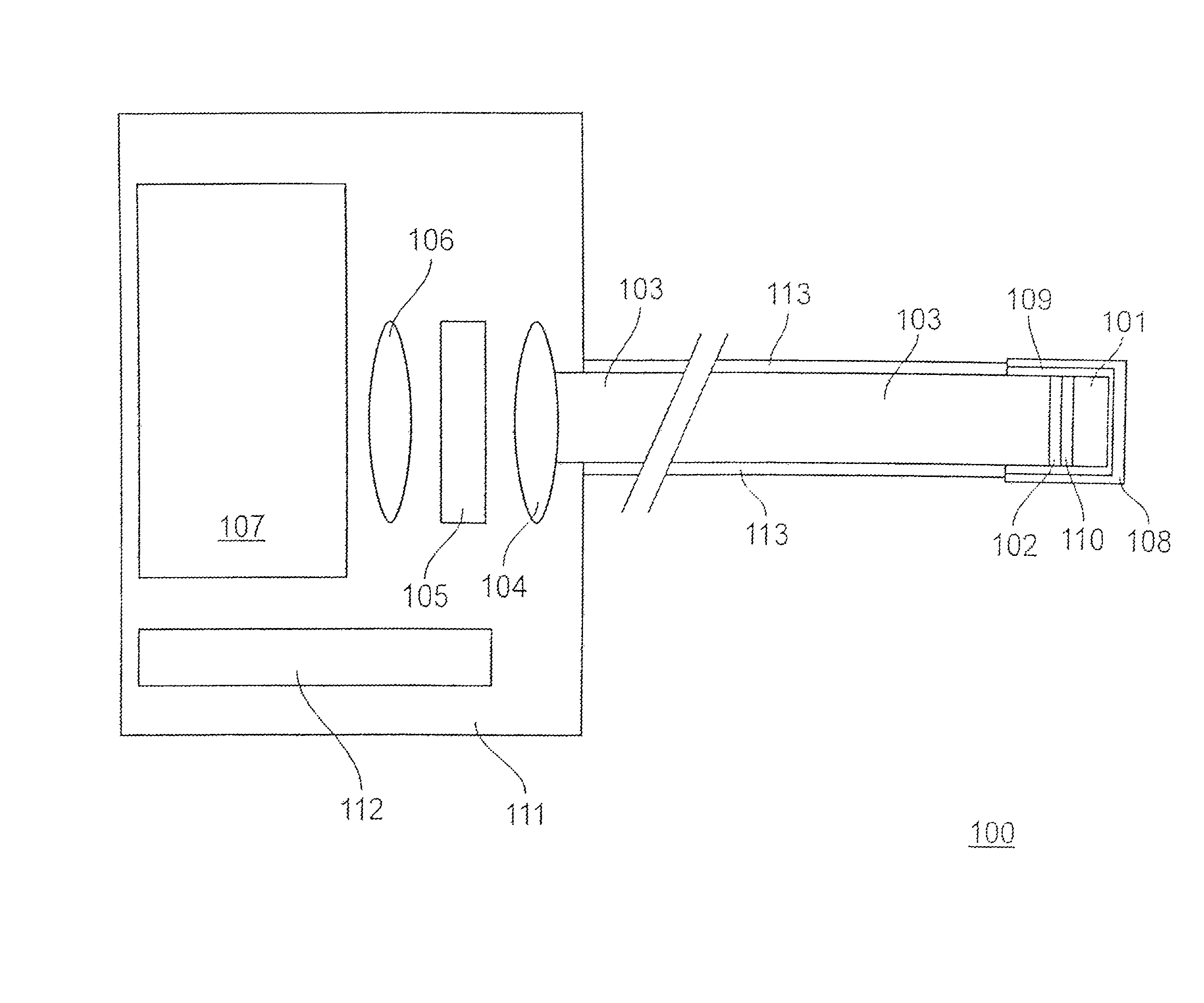
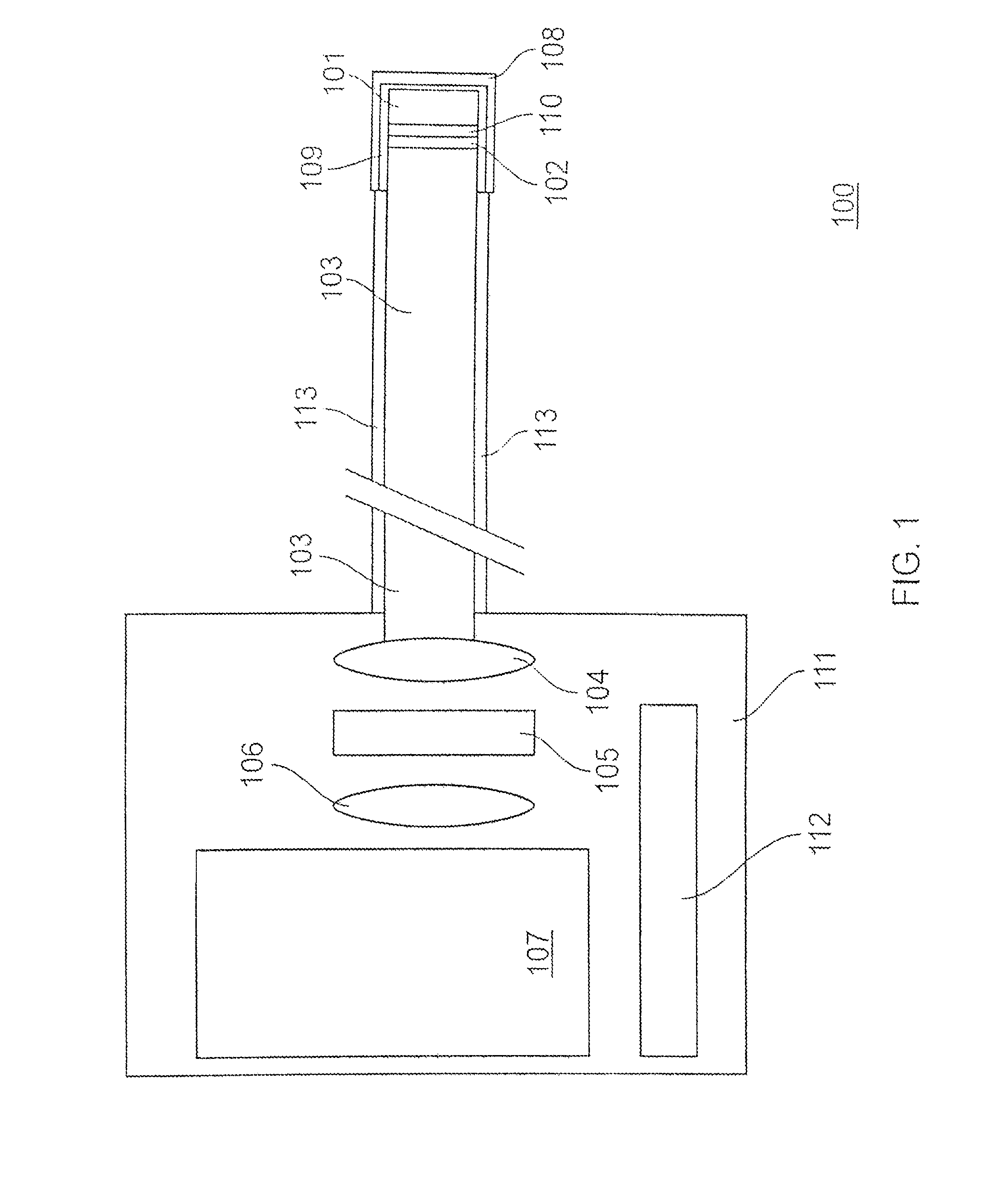
[0045]the invention will now be described with reference to FIG. 1. FIG. 1 shows a radiation detection system 100. The radiation detection system 100 has a scintillator 101. The scintillator 101 is sensitive to a first radiation type. Preferably, the scintillator 101 is a microfilm of thallium-doped Caesium Iodide (CsI:Tl). More preferably, for imaging the beta particles from fluorine-18 the microfilm of CsI:Tl is between 100 and 150 micrometers thick. This is the optimum thickness for detecting beta radiation from fluorine-18 whilst minimising interactions with gamma particles. The scintillator may be thicker for radioisotopes with higher beta energy.

[0046]The skilled reader will understand that different scintillator materials may be preferable when imaging different radiation sources. The preferred scintillator 101 must have a high light output in response to the incident radiation of interest (high efficacy). Additionally, the preferred scintillator may be selected on the amount...

second embodiment

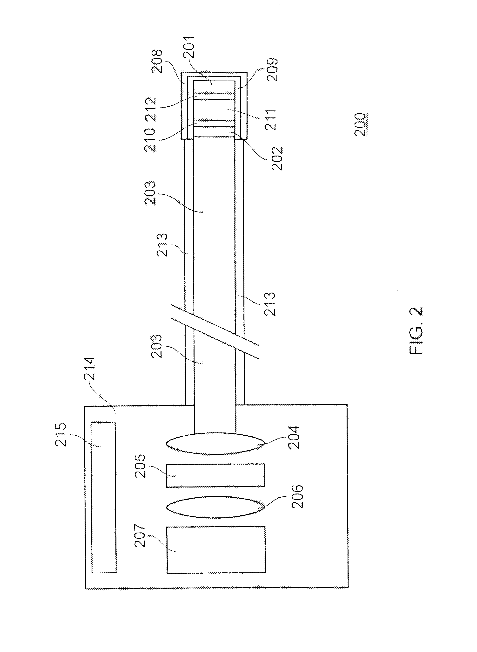
[0106]A further embodiment will now be described with reference to FIG. 3. In some applications, for example laparoscopic surgery, it is preferable to have an angled detector head. In laparoscopic surgery, an angled detector head would allow for easier viewing of the sides of the surgical cavity. FIG. 3 is a schematic diagram showing a schematic representation of a further detector head arrangement. To aid clarity, only the fibrescope detector head is shown; the skilled person will understand that the complete fibrescope system would include all of the other elements shown in the previous embodiments. Furthermore, the skilled person would also understand that this embodiment can equally be applied to the dual scintillator arrangement described in the second embodiment, with the addition of a second scintillator separated from the first scintillator by an optical index matching material.

[0107]The radiation detection system 300 has a scintillator 301. The scintillator 301 is sensitive...


PUM


Abstract

A fiberscope comprises a scintillator arranged to produce light of a first wavelength upon exposure to radiation; an optical system arranged to receive and direct light of the first wavelength emitted from the scintillator, the light being received at one end of the optical system, and wherein one or more elements of the optical system emits scintillation light of a second wavelength upon exposure to radiation; and an optical filter, disposed at the other end of the optical system, and arranged to transmit light of the first wavelength and block light of the second wavelength. The scintillator is chosen such that the light of the first wavelength is spectrally distinct from the light of the second wavelength.

Description

CROSS-REFERENCE TO RELATED APPLICATIONS[0001]The present application claims priority to UK Patent Application No. 1417449.4 filed Oct. 2, 2014, the contents of which are incorporated by reference herein in their entirety.TECHNICAL FIELD[0002]The present invention relates to the field of radiation imaging. In particular, the present invention relates to a method and apparatus for discrimination between radiation of interest and background noise.BACKGROUND TO THE INVENTION AND PRIOR ART[0003]Imaging of radiation has applications ranging from medical imaging to geophysical mapping. It is often desirable to image a radioactive source using a fibre optic camera. Imaging with a fibre optic camera allows the imaging device to be more compact, flexible and easier to handle, and allows the signal to be relayed to a shielded high-performance camera. However, the use of fibre optics in proximity to a radiation source creates noise artefacts due to the radiation interacting with the glass in th...

Claims


Application Information

Patent Timeline
Patent Type & Authority Patents(United States)
IPC IPC(8): G01T1/20G01T1/161G01T1/36
CPCG01T1/2002G01T1/161G01T1/201G01T1/2018G01T1/362A61B1/00165G01T1/202G01T1/2985
Inventor GREEN, ALANKUNAL, VYASTUCH, DAVID
Owner LIGHTPOINT SURGICAL LTD
Why Eureka
Try Eureka