
Energetic material initiation device utilizing exploding foil initiated ignition system with secondary explosive material

a technology of initiation device and initiation device, which is applied in the direction of electric fuzes, weapons, ammunition fuzes, etc., can solve the problems of disadvantageous mechanisms that move the initiator between an out-of-alignment position and an in-line position

Active Publication Date: 2008-10-07
REYNOLDS SYST
View PDF10 Cites 36 Cited by
  • Summary
  • Abstract
  • Description
  • Claims
  • Application Information

AI Technical Summary

Problems solved by technology

Mechanisms that move an initiator between an out-of-alignment position and an in-line position are generally disadvantageous due to considerations for cost, weight and reliability.

Method used


Image

  • Energetic material initiation device utilizing exploding foil initiated ignition system with secondary explosive material
  • Energetic material initiation device utilizing exploding foil initiated ignition system with secondary explosive material
  • Energetic material initiation device utilizing exploding foil initiated ignition system with secondary explosive material

Examples


Embodiment Construction

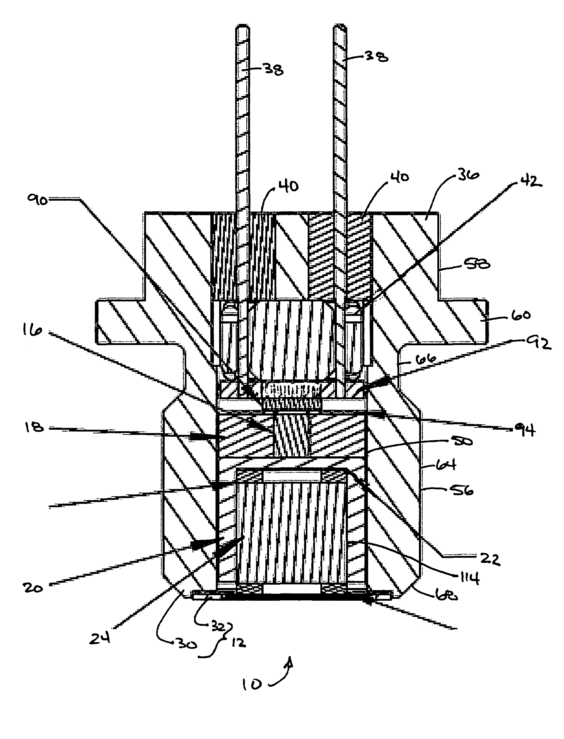
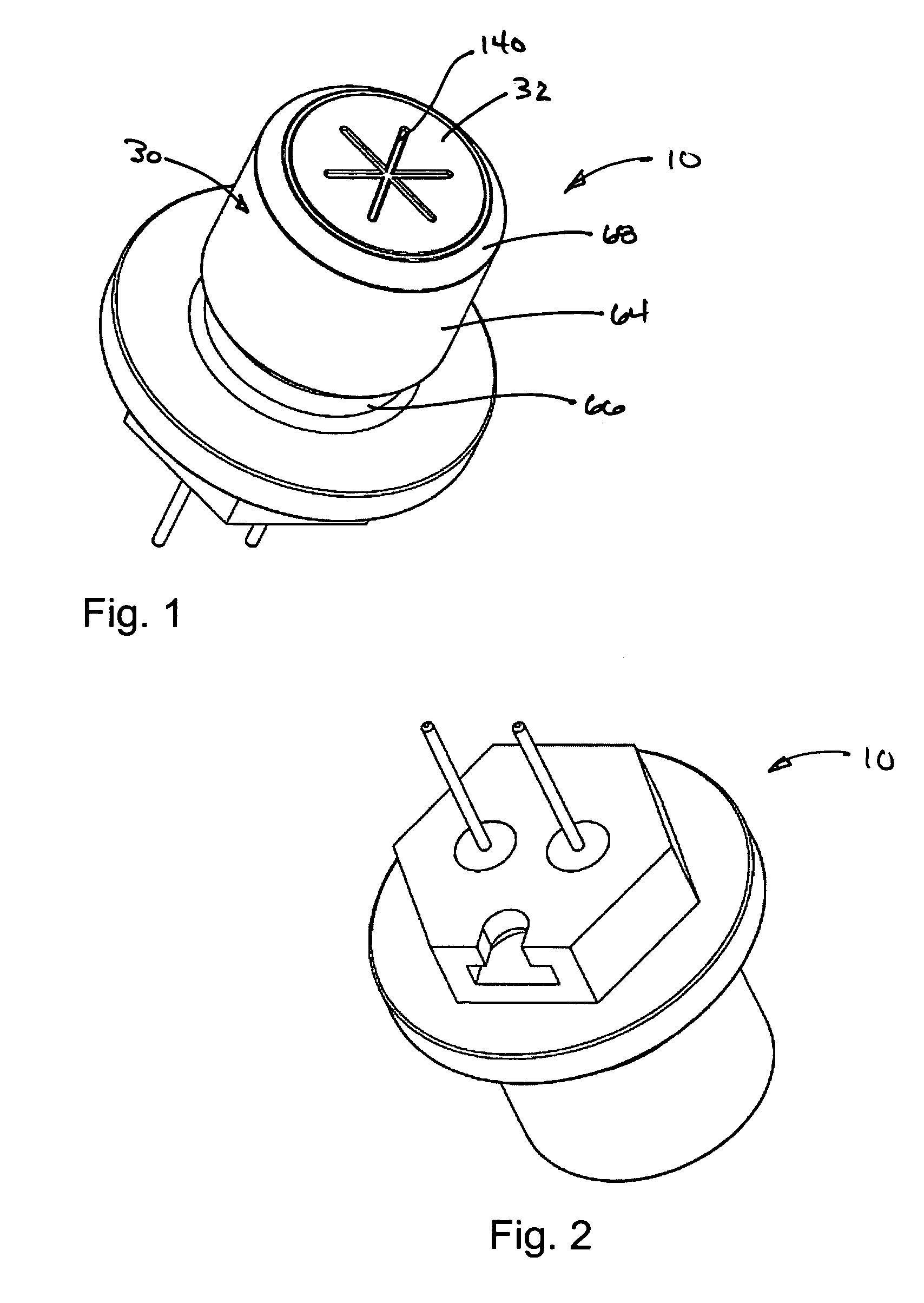
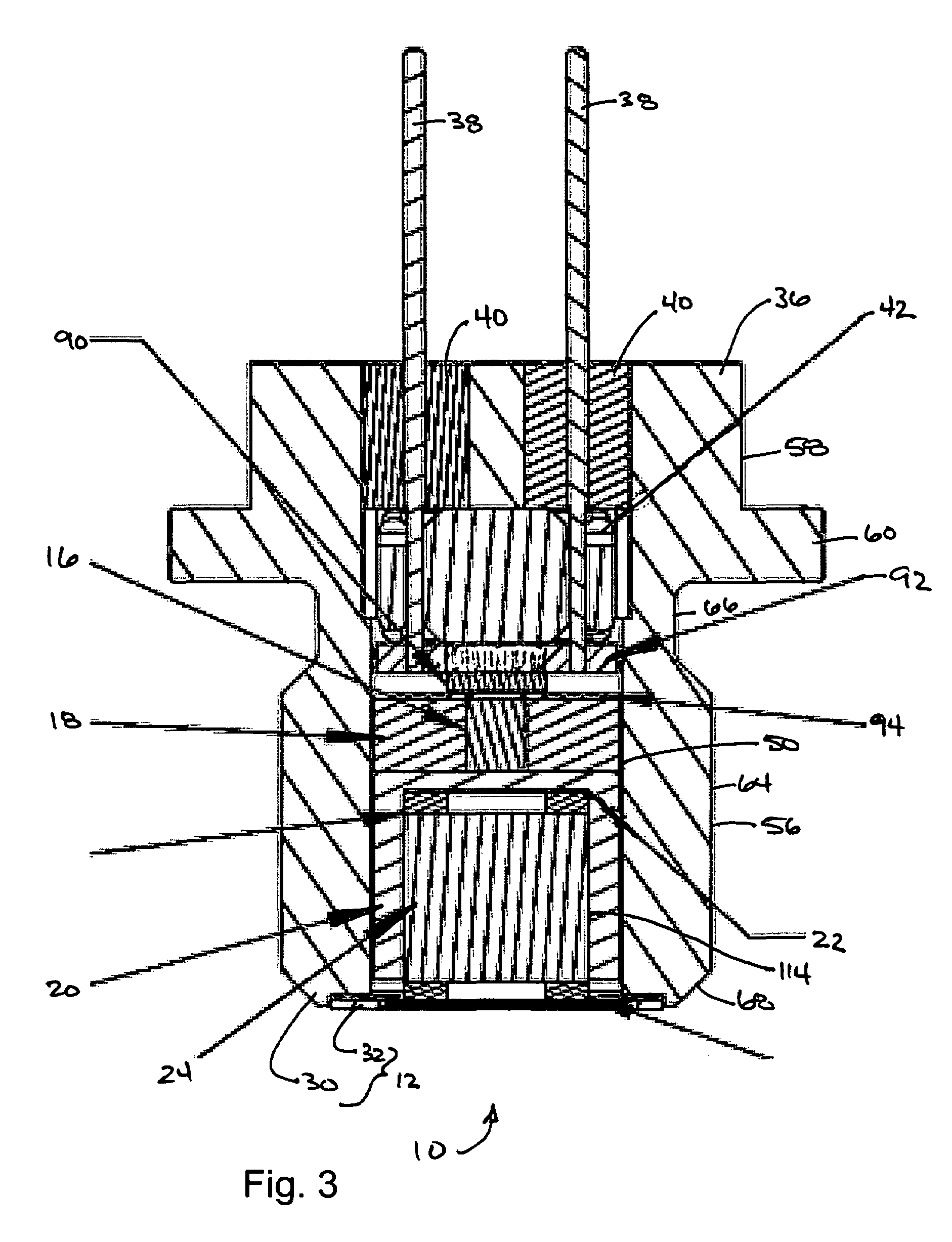
[0022]With reference to FIGS. 1 through 4 of the drawings, an energetic material initiation device constructed in accordance with the teachings of the present disclosure is generally indicated by reference numeral 10. The energetic material initiation device 10 can include a housing assembly 12, an initiator assembly 14, an input charge 16, a sleeve 18, a first barrier structure 20, a second barrier structure 22 and an output charge 24. In the particular example provided, the housing assembly 12 includes a base assembly 30 and a cover 32.

[0023]With reference to FIGS. 3 through 5, the base assembly 30 can include a housing 36, a plurality of electric contacts 38, a plurality of seal members 40 and a spacing member 42. The housing 36 can be formed of any suitable material, such as 304 stainless, and can have an input end 46, an output end 48, an internal cavity 50, and a plurality of seal apertures 52. The internal cavity 50 can be formed through the output end 48 and can terminate fo...


PUM


Abstract

An igniter assembly with a housing, an initiator, an input charge, a first barrier, a second barrier, and an output charge. The input charge is formed of a secondary explosive and disposed adjacent the initiator. The first barrier cooperates with the housing to form a chamber into which the input charge is received. The second barrier is disposed on a side of the first barrier opposite the input charge and combusts in response to energy released during detonation of the input charge. The output charge is formed of a pyrotechnic material and disposed on a side of the second barrier opposite the first barrier. The output charge can combust in response to energy released during combustion of the second barrier. The housing and the first barrier cooperate to isolate the output charge from heat and pressure generated by the input charge if the input charge is cooked-off.

Description

INTRODUCTION[0001]The present invention generally relates to energetic material initiation devices and more particularly to an energetic material initiation device that when activated can produce a deflagration output having a high pressure, high temperature impulse and that when inactivated can absorb a relatively high voltage and current electrical input without ejecting matter from the output end of the initiation device.[0002]Devices, such as rocket motors, employ initiators for producing a pyrotechnic output for initiating combustion. Known initiators are typically activated via a relatively low energy electric impulse and thus maintained out of alignment with the device until activation of the initiator is desired. Mechanisms that move an initiator between an out-of-alignment position and an in-line position are generally disadvantageous due to considerations for cost, weight and reliability. Additionally, the known initiators typically produce output pressures of about 200 to...

Claims


Application Information

Patent Timeline
Patent Type & Authority Patents(United States)
IPC IPC(8): F42C19/12F42B3/10
CPCF42B3/103F42B3/127
Inventor HENNINGS, GEORGE N.REYNOLDS, RICHARD K.NANCE, CHRISTOPHER J.
Owner REYNOLDS SYST
Learn More