Fuel injection system monitoring abnormal pressure in inlet of fuel pump

a fuel pump and inlet pressure technology, applied in the direction of fuel injecting pumps, machines/engines, electric control, etc., can solve the problems of increasing the total production cost of the system, the need for creasing a space, and the difficulty in regulating the pressure at the inlet of the high-pressure supply pump

Active Publication Date: 2008-10-07
DENSO CORP
View PDF11 Cites 16 Cited by
  • Summary
  • Abstract
  • Description
  • Claims
  • Application Information

AI Technical Summary

Benefits of technology

[0011]It is another object of the invention to provide a fuel injection system equipped with a high-pressure supply pump and a low-pressure supply pump which is designed to monitor an abnormal pressure of fuel at an inlet of the high-pressure supply pump indirectly in a simple manner.

Problems solved by technology

The use of the pressure sensor, however, results in an increase in total production cost of the systems and a need for creasing a space for installation of the sensor.
Such techniques are suitable for regulating the pressure at the outlet of the high-pressure supply pump, but have a difficulty in regulating the pressure at the inlet of the high-pressure supply pump.

Method used


Image

  • Fuel injection system monitoring abnormal pressure in inlet of fuel pump
  • Fuel injection system monitoring abnormal pressure in inlet of fuel pump
  • Fuel injection system monitoring abnormal pressure in inlet of fuel pump

Examples


first embodiment

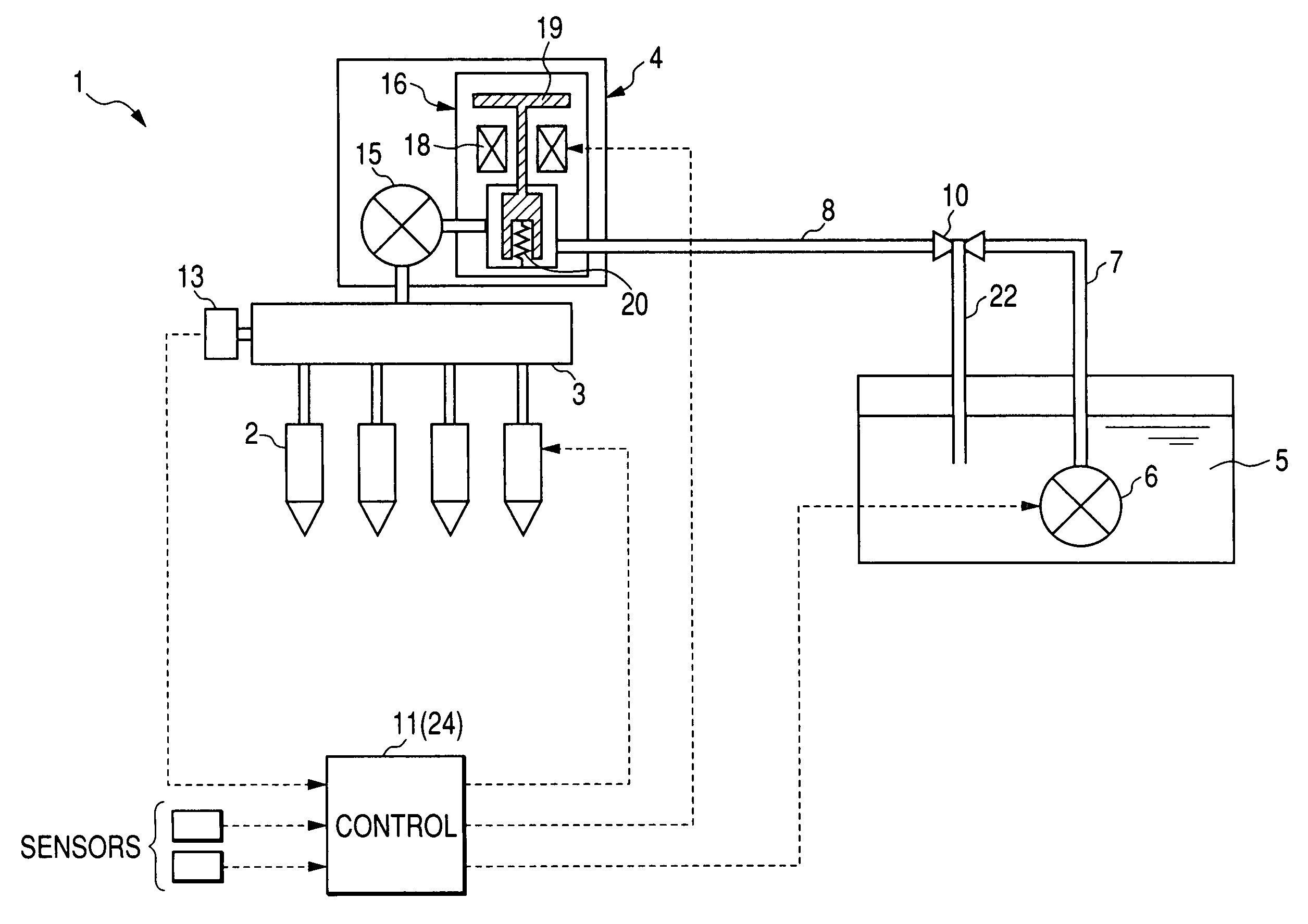
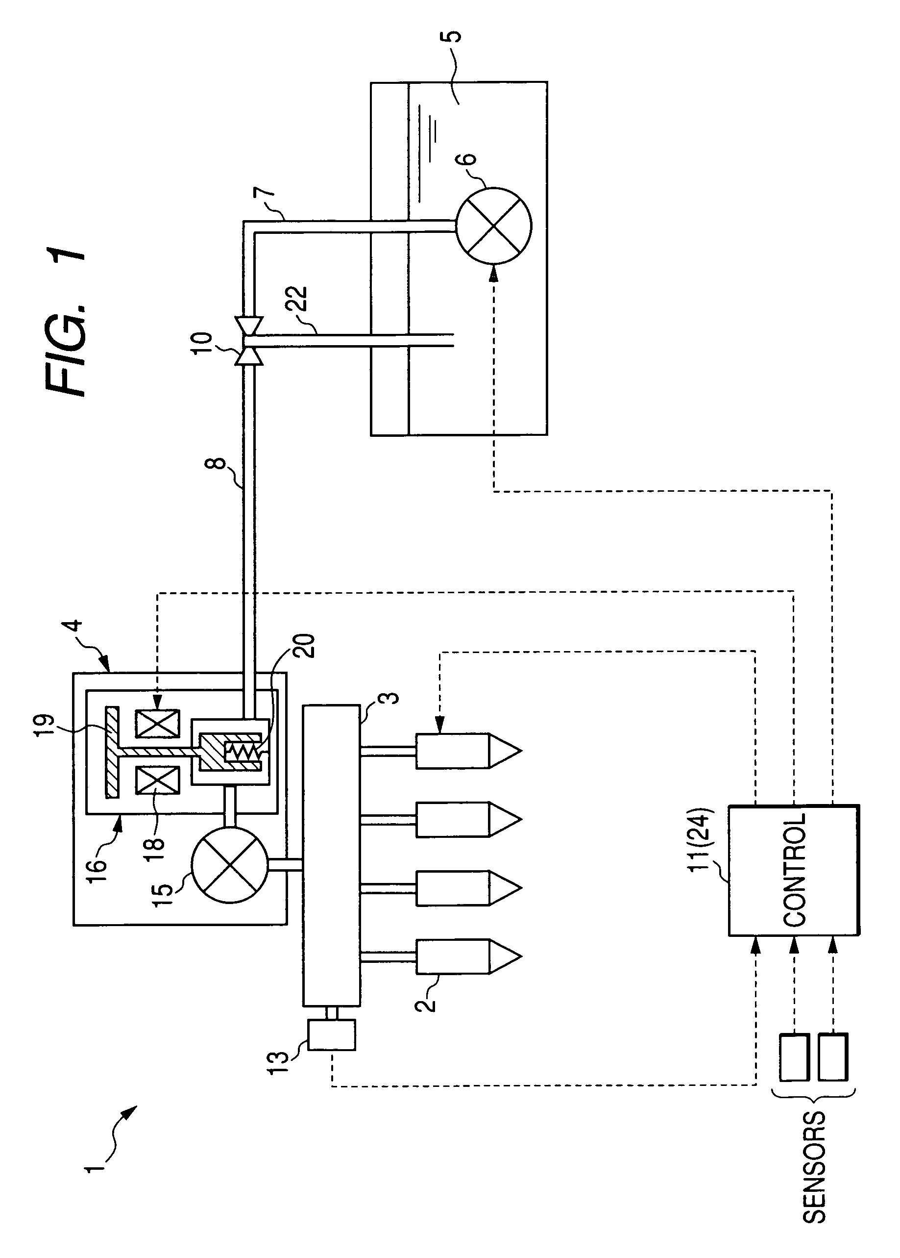
[0025]Referring to the drawings, wherein like reference numbers refer to like parts in several views, particularly to FIG. 1, there is shown a fuel injection system 1 according to the invention which is designed to inject fuel into cylinders of direct injection engines such as diesel engines.

[0026]The fuel injection system 1 consists essentially of injectors 2, one for each cylinder of the engine, a common rail 3, a high-pressure supply pump 4, a low-pressure supply pump 6, a pressure regulator 10, and a controller 11. The pressure regulator 10 is disposed between fuel flow paths 7 and 8 extending from the low-pressure supply pump 6 to the high-pressure supply pump 4. The low-pressure supply pump 6 is driven by a power source other than the engine to suck the fuel from a fuel tank 6 and supply it to the high-pressure supply pump 4 through the pressure regulator 10. The pressure regulator 10 regulates the pressure of the fuel discharged out of the low-pressure supply pump 6 to the hi...

second embodiment

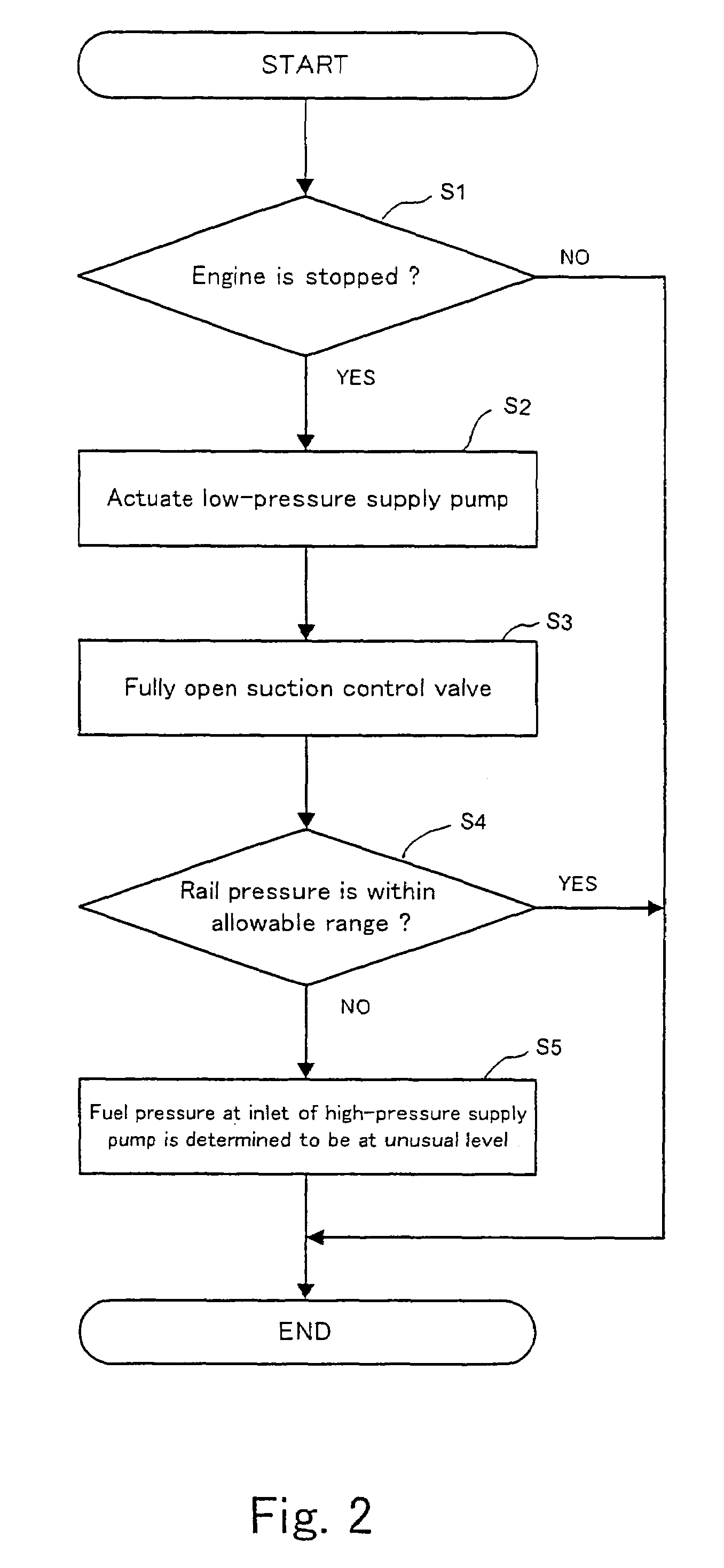
[0053]The fuel injection system of the invention which is designed to monitor an SCV position parameter that is a parameter changing as a function of the SCV open position (i.e., the open position of the SCV 16) during idle modes of engine operation to determine whether the pressure of fuel at the inlet of the high-pressure supply pump 4 is in an unusual level or not.

[0054]The SCV position parameter may be one of the command value (i.e., a target value) of the SCV open position, as calculated in the controller 11, the command value of amount of energization of the solenoid coil 18 required to achieve the command value of the SCV open position, a duty cycle of the drive signal required to achieve the command value of amount of energization of the solenoid coil 18, a difference between a measured value of the rail pressure and the target rail pressure and a ratio therebetween.

[0055]FIG. 3 is a flowchart of logical steps or program to be executed by the controller 11 to monitor the lev...


PUM


Abstract

A fuel injection system is equipped with a high-pressure supply pump driven by an output of an internal combustion engine to supply fuel to an accumulator, a low-pressure supply pump driven by a power source other than the engine to suck the fuel from a fuel tank and supply the sucked fuel to the high-pressure supply pump, and a pressure regulator working to regulate the pressure of the fuel supplied from the low-pressure supply pump to the high-pressure supply pump. The system also includes an abnormal pressure detector working to monitor a preselected parameter that bears a correlation to the energy held by the fuel at an inlet of the high-pressure supply pump to detect whether a pressure of the fuel at the inlet of the high-pressure supply pump is in an abnormal level or not without monitoring it directly.

Description

CROSS REFERENCE TO RELATED DOCUMENT[0001]The present application claims the benefit of Japanese Patent Application No. 2005-209144 filed on Jul. 19, 2005, the disclosure of which is incorporated herein by reference.BACKGROUND OF THE INVENTION[0002]1. Technical Field of the Invention[0003]The present invention relates generally to a fuel injection system such as a common rail system (also called an accumulator fuel injection system) for automotive diesel engines which is designed to spray jets of high-pressure fuel supplied from an accumulator into cylinders of the engine through fuel injectors, and more particularly, to such a system designed to monitor an abnormal pressure of fuel sucked into a fuel pump for supplying the fuel to the accumulator.[0004]2. Background Art[0005]There are known accumulator fuel injection systems which are equipped with a common rail in which fuel is accumulated at a target pressure, as determined as a function of an operating condition of an internal co...

Claims


Application Information

Patent Timeline
Patent Type & Authority Patents(United States)
IPC IPC(8): F02M63/00
CPCF02D41/221F02D41/3854F02M59/366F02M63/0225F02M65/003F02D41/042F02D2200/0604F02D2250/31
Inventor TSUJIMOTO, SUSUMU
Owner DENSO CORP
Why Eureka
Try Eureka