
Bicycle wheel hub cover

a technology for bicycle wheels and hub covers, which is applied in the direction of bicycle equipment, guards, transportation and packaging, etc., can solve the problems of incompatibility of conventional hub covers with some wheels, contact with spokes too strongly, and the hub cover will not match the slant angle of some wheels

Inactive Publication Date: 2008-10-07
SHIMANO INC
View PDF38 Cites 3 Cited by
  • Summary
  • Abstract
  • Description
  • Claims
  • Application Information

AI Technical Summary

Benefits of technology

The present invention provides a hub cover for bicycles that can be easily attached to different wheel configurations, regardless of the spoke configuration. The hub cover is attached to the hub using the hub flange and the hub shell, making it secure and easy to install. The hub cover can be easily detached and re-attached, and it is designed to prevent the chain from coming off the sprocket and to make it difficult for the chain to contact the spokes. The hub cover can be attached to the hub shell in a freely detachable and re-attachable manner. Overall, the hub cover provides a simple and effective solution for attaching a hub cover to a bicycle.

Problems solved by technology

Consequently, there is the possibility that the conventional hub cover will be incompatible with some wheels (i.e., not be attachable to some wheels) due to the configuration of the spokes.
For example, since the degree of slant (i.e., slant angle) of the spokes varies depending on the internal diameter of the rim, there is the possibility that the hub cover will not match the slant angle of the spokes of some wheels.
If the hub cover does not match the slant angle of the spokes, the inward surface of the outer circumferential portion of the main body might not contact the spokes or the inward surface might contact the spokes too strongly and exert unnecessary force against the spokes.

Method used


Image

  • Bicycle wheel hub cover
  • Bicycle wheel hub cover
  • Bicycle wheel hub cover

Examples


Embodiment Construction

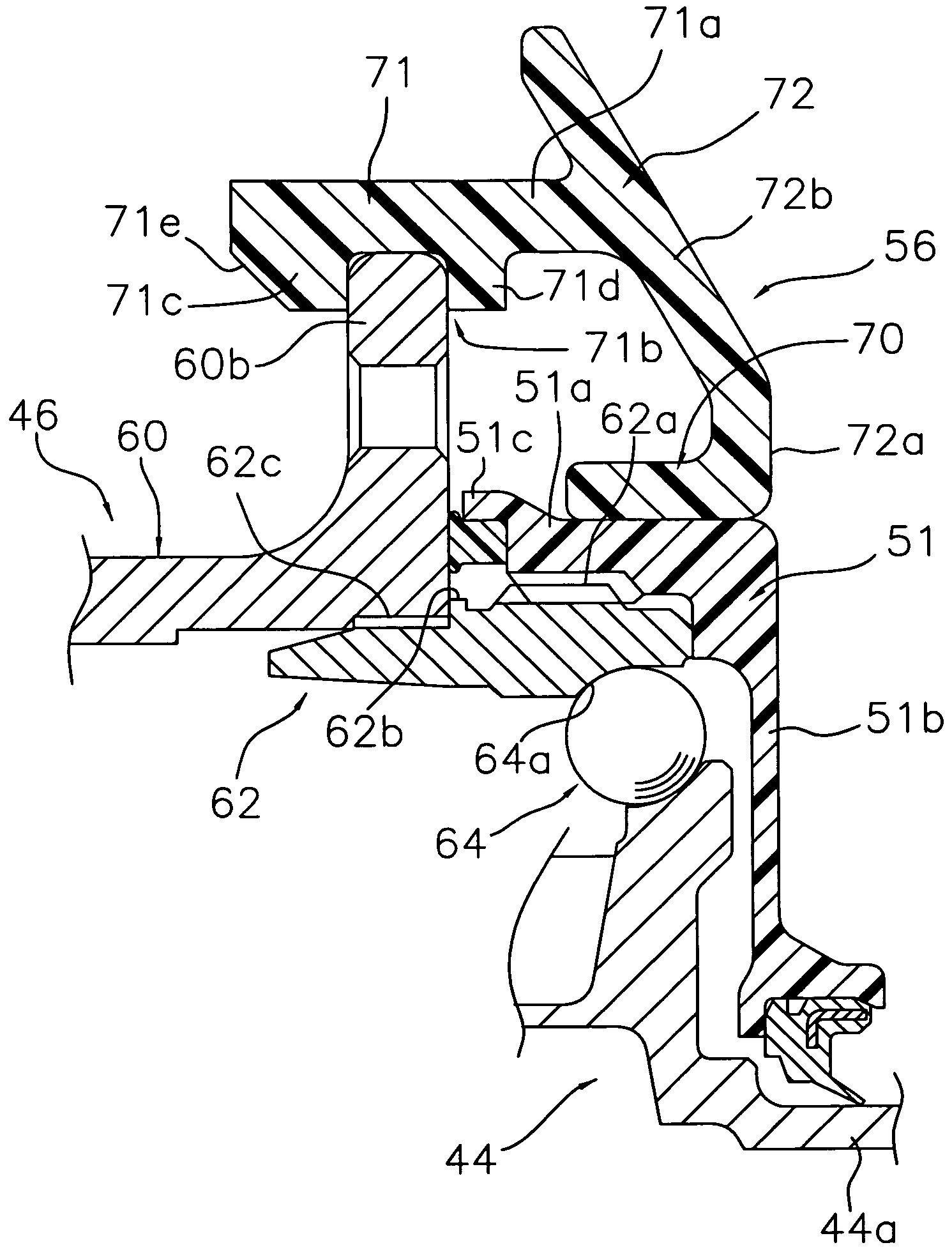
[0027]Selected embodiments of the present invention will now be explained with reference to the drawings. It will be apparent to those skilled in the art from this disclosure that the following descriptions of the embodiments of the present invention are provided for illustration only and not for the purpose of limiting the invention as defined by the appended claims and their equivalents.

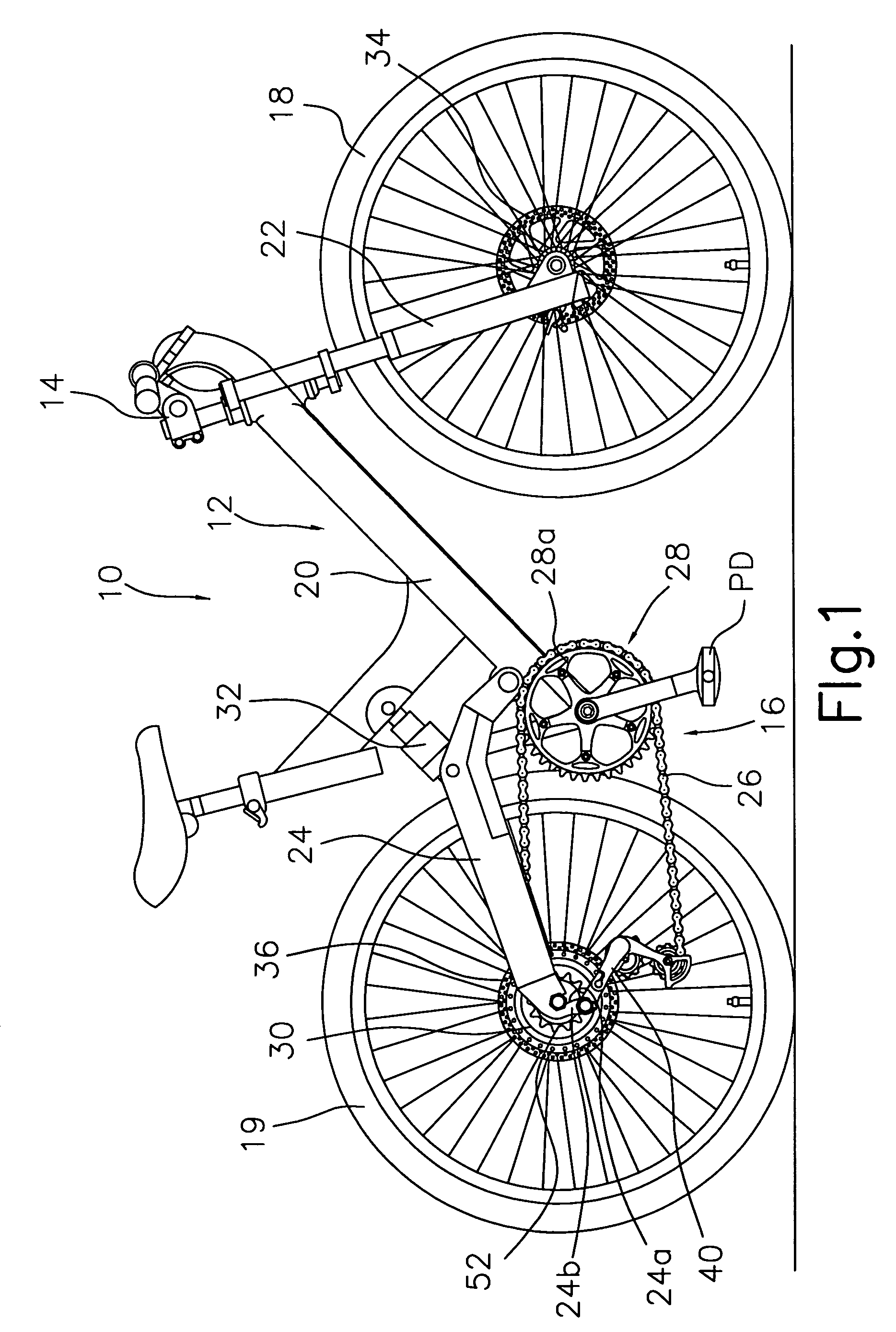
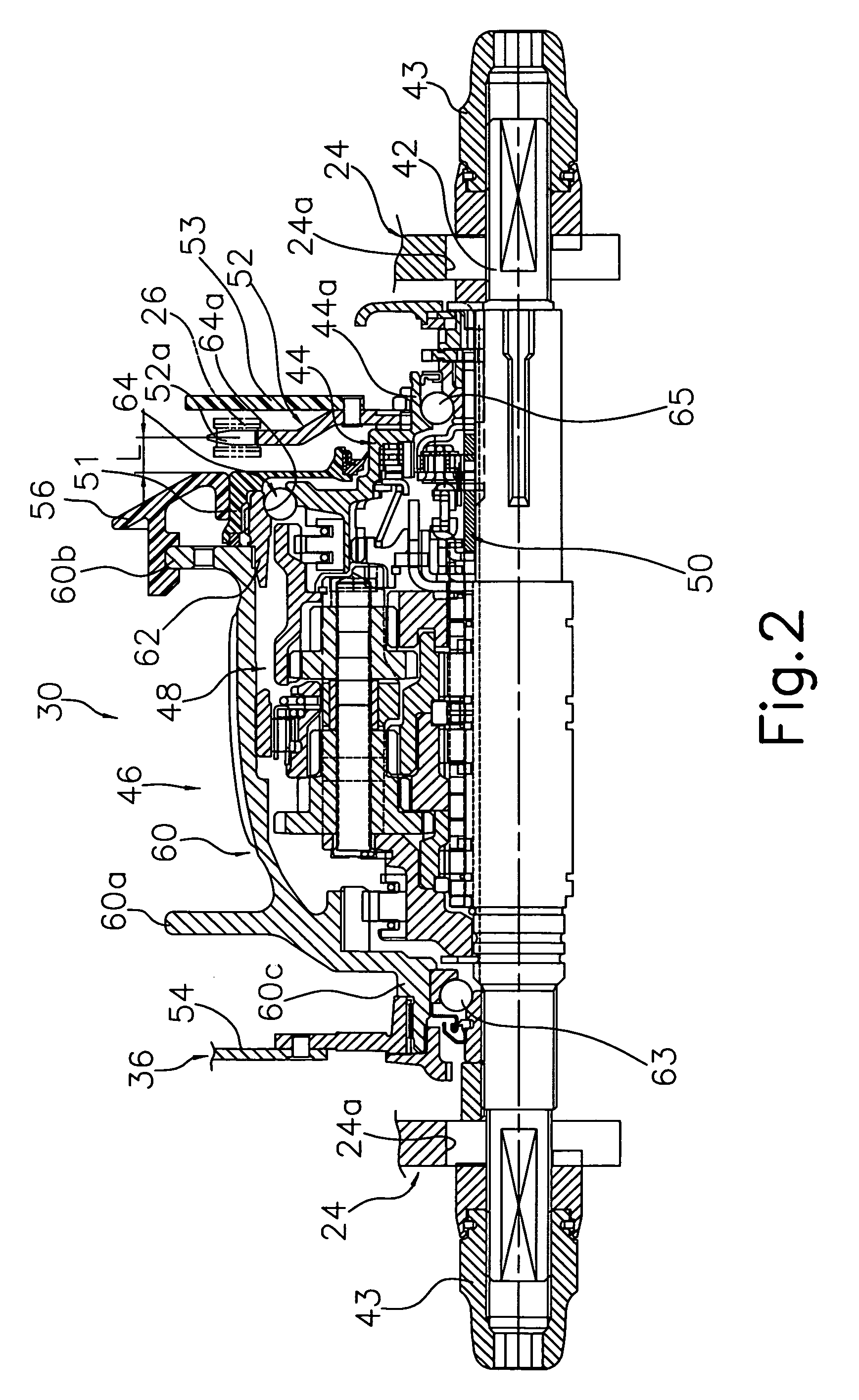
[0028]Referring initially to FIG. 1, a bicycle 10 is illustrated that is equipped in accordance with a first embodiment of the present invention. The bicycle 10 basically includes a frameset 12, a handlebar unit 14, a drive unit 16, a front wheel 18 and a rear wheel 19. The frameset 12 has a frame 20, a suspension fork 22, and a rear suspension or swing arm 24. The handlebar unit 14 is fastened to the suspension fork 22. The drive unit 16 basically includes a chain 26, a crankset 28, an internally geared rear hub 30, and other components. The crankset 28 includes a pair of pedals PD and a front spr...


PUM


Abstract

A hub cover is configured to be mounted to a wheel regardless of the spoke configuration of the wheel. The bicycle hub cover is capable of being attached to a bicycle hub that has a hub shell. The hub shell has a hub flange and a cap member. The hub cover comprises a cylindrical part, a retaining part, and a connecting part. The cylindrical part is capable of being attached to the cap member, which is mounted to the hub shell on the axially outward side of the hub flange. The retaining part is configured to latch onto the hub flange. The connecting part is configured to extend radially outward from the cylindrical part and connect the cylindrical part and the retaining part together.

Description

[0001]This application claims priority under 35 U.S.C. § 119 to Japanese Patent Application No. 2005-220734. The entire disclosure of Japanese Patent Application No. 2005-220734 is hereby incorporated herein by reference.BACKGROUND OF THE INVENTION[0002]1. Field of the Invention[0003]This invention generally relates to a bicycle hub cover. More specifically, the present invention relates to a bicycle hub cover configured and arranged to be attached to a hub of a bicycle.[0004]2. Background Information[0005]Bicycling is becoming an increasingly more popular form of recreation as well as a means of transportation. Moreover, bicycling has become a very popular competitive sport for both amateurs and professionals. Whether the bicycle is used for recreation, transportation or competition, the bicycle industry is constantly improving the various components of the bicycle. One component that has been extensively redesigned is the bicycle drive train.[0006]A bicycle hub is generally provid...

Claims


Application Information

Patent Timeline
Patent Type & Authority Patents(United States)
IPC IPC(8): B60B7/00B62J13/00B62J23/00B62M9/128
CPCB60B7/0013B60B7/06B60B7/061B60B27/0005B60B27/0047B60B27/0052B60B27/0073B60B27/023B60B27/04B60B35/004B60B35/04B62J23/00
Inventor URABE, HIROYUKI
Owner SHIMANO INC
Learn More