
Power distribution branch unit and vehicle

a power distribution branch unit and power distribution branch technology, applied in the direction of current conducting connection, cell component, coupling device connection, etc., can solve the problems of large size of each connector, limited layout of the power distribution branch unit, and problem not only in electric vehicles but also in other devices or structures, etc., to achieve easy maintenance, suppress tension and/or twist, and maintain the connection in the connection part.

Active Publication Date: 2019-03-21
HONDA MOTOR CO LTD
View PDF9 Cites 4 Cited by
  • Summary
  • Abstract
  • Description
  • Claims
  • Application Information

AI Technical Summary

Benefits of technology

The present invention aims to provide a vehicle and power distribution branch unit that offer better flexibility in layout and minimization. The invention achieves at least one of improved flexibility and miniaturization.

Problems solved by technology

Thus, the layout in the power distribution branch unit is limited.
Therefore, the size becomes large by each connector.
Such a problem occurs not just in electric vehicles but also in other devices or structures that use power distribution branch units.

Method used


Image

  • Power distribution branch unit and vehicle
  • Power distribution branch unit and vehicle
  • Power distribution branch unit and vehicle

Examples


first embodiment

A. First Embodiment

[A-1-1. Overall Structure]

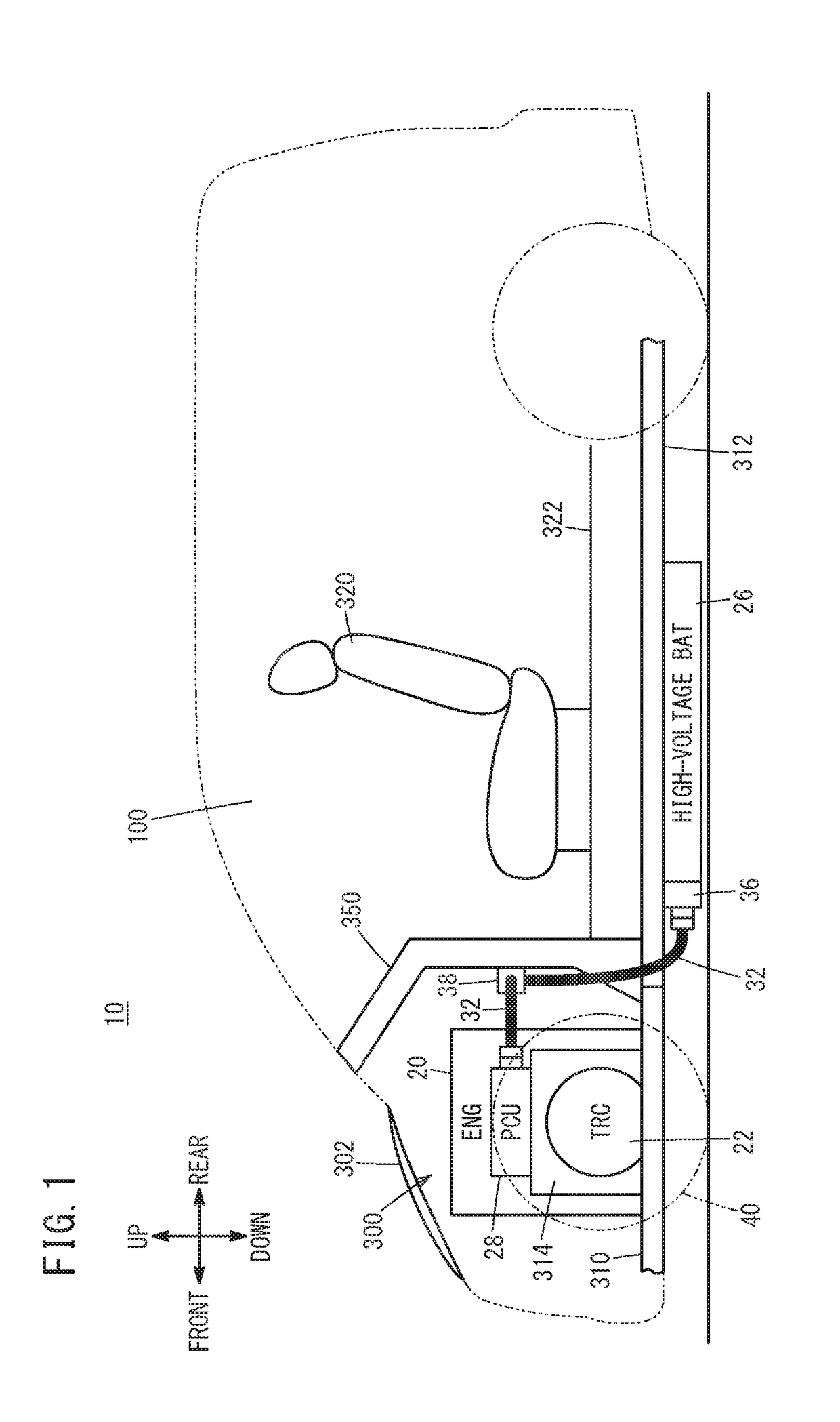
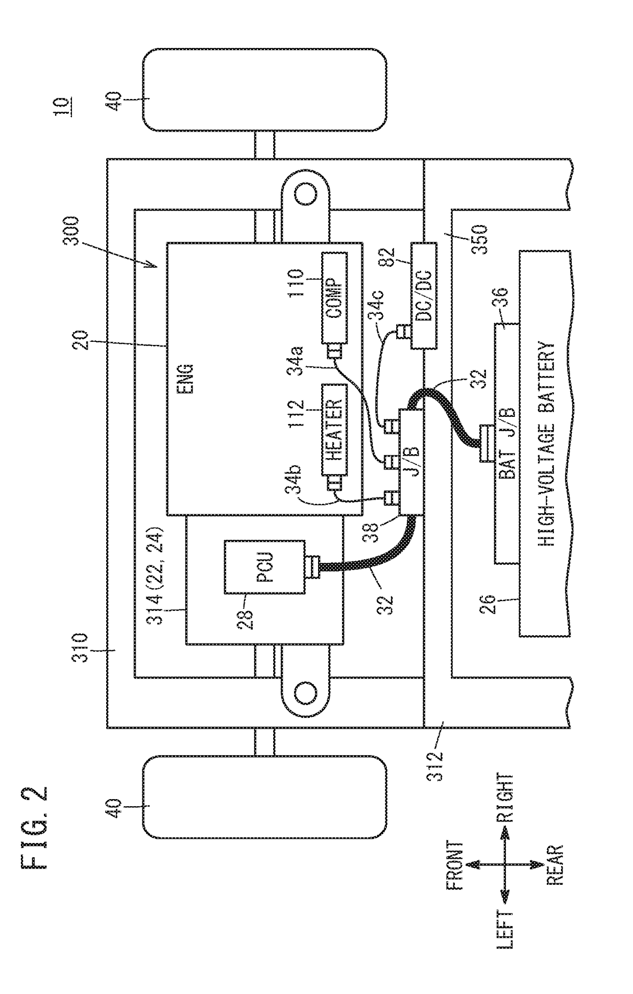
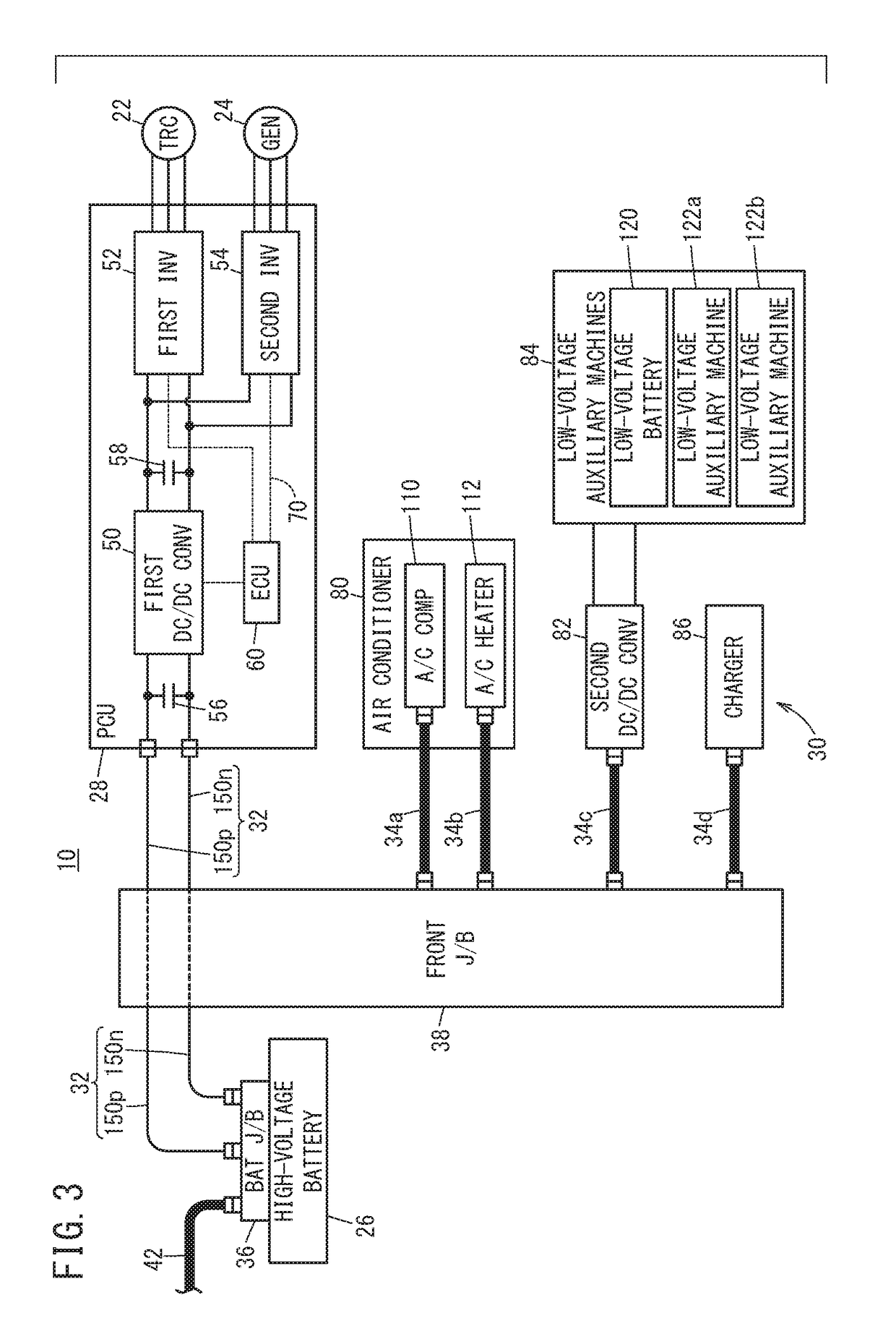
[0035]FIG. 1 is a side view that schematically illustrates the structure of a vehicle 10 including a front junction box 38 as a power distribution branch unit according to a first embodiment of the present invention. FIG. 2 is a plan view that schematically illustrates the structure of a front side of the vehicle 10 according to the first embodiment. FIG. 3 is an electric circuit diagram that illustrates electric connections in the vehicle 10 according to the first embodiment.

[0036]As illustrated in FIG. 1 to FIG. 3, the vehicle 10 includes, in addition to the front junction box 38, an engine 20, a travel motor 22, a generator 24, a high-voltage battery 26 (hereinafter, also referred to as “battery 26” or “BAT 26”), a power control unit 28 (hereinafter, referred to as “PCU 28”), electric auxiliary machines 30 (FIG. 3), main wiring 32, auxiliary machine wirings 34a to 34d (FIG. 3), and a battery junction box 36.

[0037]The vehicle 10 is a hy...

second embodiment

B. Second Embodiment

[0106]FIG. 9 is a cross-sectional view that schematically illustrates a part of the structure of the main wiring 32 and a front junction box 38a according to a second embodiment. The structure of a vehicle 10A according to the second embodiment is basically the same as the structure of the vehicle 10 according to the first embodiment. Hereinafter, the same reference signs denote the common components in the first embodiment and the second embodiment, and detailed description thereof is not repeated.

[0107]In the first embodiment, the main covered cables 150p, 150n are fixed by the branch wiring 162, the retainers 166, and the grommets 168 (FIG. 4, FIG. 5). On the other hand, in the front junction box 38a according to the second embodiment, the main covered cables 150p, 150n are fixed by internal fixing members 360, in addition to the branch wirings 162, the retainers 166, and the grommets 168.

[0108]FIG. 10 schematically illustrates a connection part 370 between th...


PUM


Abstract

In a case of a power distribution branch unit used in a vehicle or the like, one end of a branch wiring is connected to an exposed part of a main covered cable (a part where a core wire is exposed without an insulation cover). Branch couplers are connected to the other ends of the branch wiring and fixed to the case so as to be exposed to an outside. At least one retainer is disposed inside a hole part that is formed in the case and fixes the main covered cable.

Description

CROSS-REFERENCE TO RELATED APPLICATION[0001]This application is based upon and claims the benefit of priority from Japanese Patent Application No. 2017-177243 filed on Sep. 15, 2017, the contents of which are incorporated herein by reference.BACKGROUND OF THE INVENTIONField of the Invention[0002]The present invention relates to a power distribution branch unit that branches current and a vehicle including the power distribution branch unit.Description of the Related Art[0003]When current is branched in an electric vehicle, a power distribution branch unit (or an electric connection box or a junction box) as disclosed in Japanese Laid-Open Patent Publication No. 2004-273381 is provided, for example. Japanese Laid-Open Patent Publication No. 2004-273381 discloses a connector fitting structure in which a connector group directly attached to an apparatus and another connector group on a counterpart side are easily fitted to and separated from each other by a turning operation of a bolt....

Claims


Application Information

Patent Timeline
Patent Type & Authority Applications(United States)
IPC IPC(8): H01R13/40H01R13/62H01R13/52H01M50/50
CPCH01R13/40H01R13/62H01R13/5208H01R13/5213H01R2201/26B60R16/0215H01M50/502H01R13/5825B60L53/18Y02T10/7072Y02T10/70Y02T90/14Y02E60/10
Inventor MURAMATSU, MIHARUYAMAGUCHI, HIROO
Owner HONDA MOTOR CO LTD
Learn More