Grounding structure of an electrical connector

a technology of grounding structure and electrical connector, which is applied in the direction of coupling device details, connection contact member materials, coupling device connections, etc., can solve the problems of increasing cost, increasing cost, and wasting manpower, so as to reduce relative cost, improve electrical characteristics, and best electrical characteristics

Inactive Publication Date: 2006-05-30
ING SHANG LUN
View PDF60 Cites 60 Cited by
  • Summary
  • Abstract
  • Description
  • Claims
  • Application Information

AI Technical Summary

Benefits of technology

[0007]According to one aspect of the present invention, the present invention provides a high frequency connector with an easy connecting part, which overcomes some, or all of the previously delineated drawbacks of the prior art connector that makes the connector to have the best electrical characteristics.
[0008]For reaching the aforesaid object, wherein, the connecting part comprises a wing portion and a protrusion portion; thereby the connecting part can engage the grounding terminals with the grounding line of the cable to form electrical contact. Furthermore, one end of the connecting part is extended directly and comprises predetermined grounding terminals, such that the grounding line can be directly connected to the connecting part; such as, the electrical connector can have better electrical characteristics and the grounding line can directly be coupled to the grounding terminals without the soldering process by using the aforesaid structure, meanwhile, the entire assembly process and the relative cost can be lessened.

Problems solved by technology

Generally, most grounding structure of the prior art connector used on the motherboard of the computer mainly is soldered directly to the grounding line and the grounding terminals, however, due to the science and technology increasing continuously and the environmental protection sense raising, the assembly process of the electronic industry is leading to lead-ness process progressively.
However, the grounding design of the connector according to the U.S. Pat. No. 6,489,563 B1 patent may improve the electrical characteristics, but it has no contribution to the environmental protection considering and assembly process; besides it easily generates environmental pollution during the soldering process, it also easily causes departing effect if the soldering process is not complete or not certain, further, decreases the grounding effect and electrical characteristics; meanwhile, the assembly structure of the prior art not only increases the cost and wastes man power, but has a poor yield rate, such that the manufacturing cost is increased for no reason and does not conform to cost effectiveness.

Method used


Image

  • Grounding structure of an electrical connector
  • Grounding structure of an electrical connector
  • Grounding structure of an electrical connector

Examples


Embodiment Construction

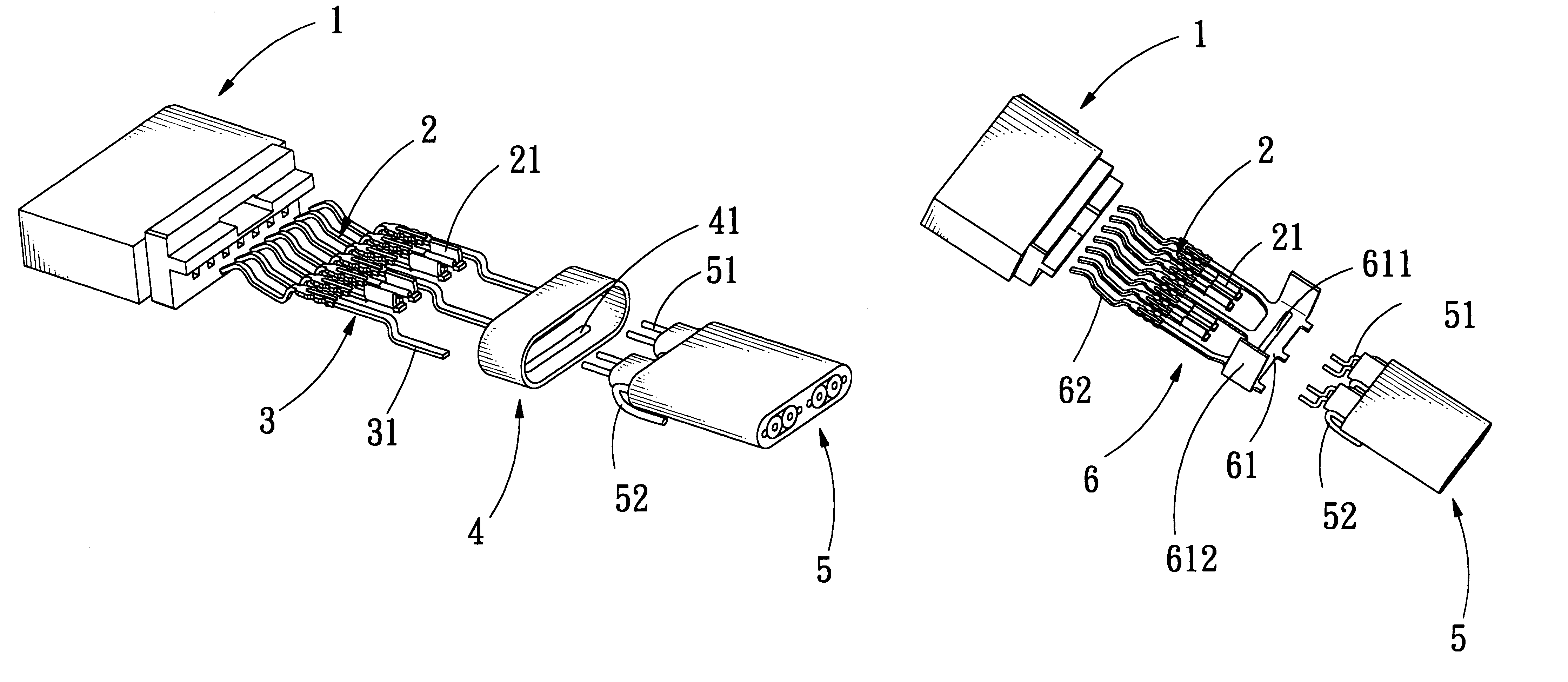
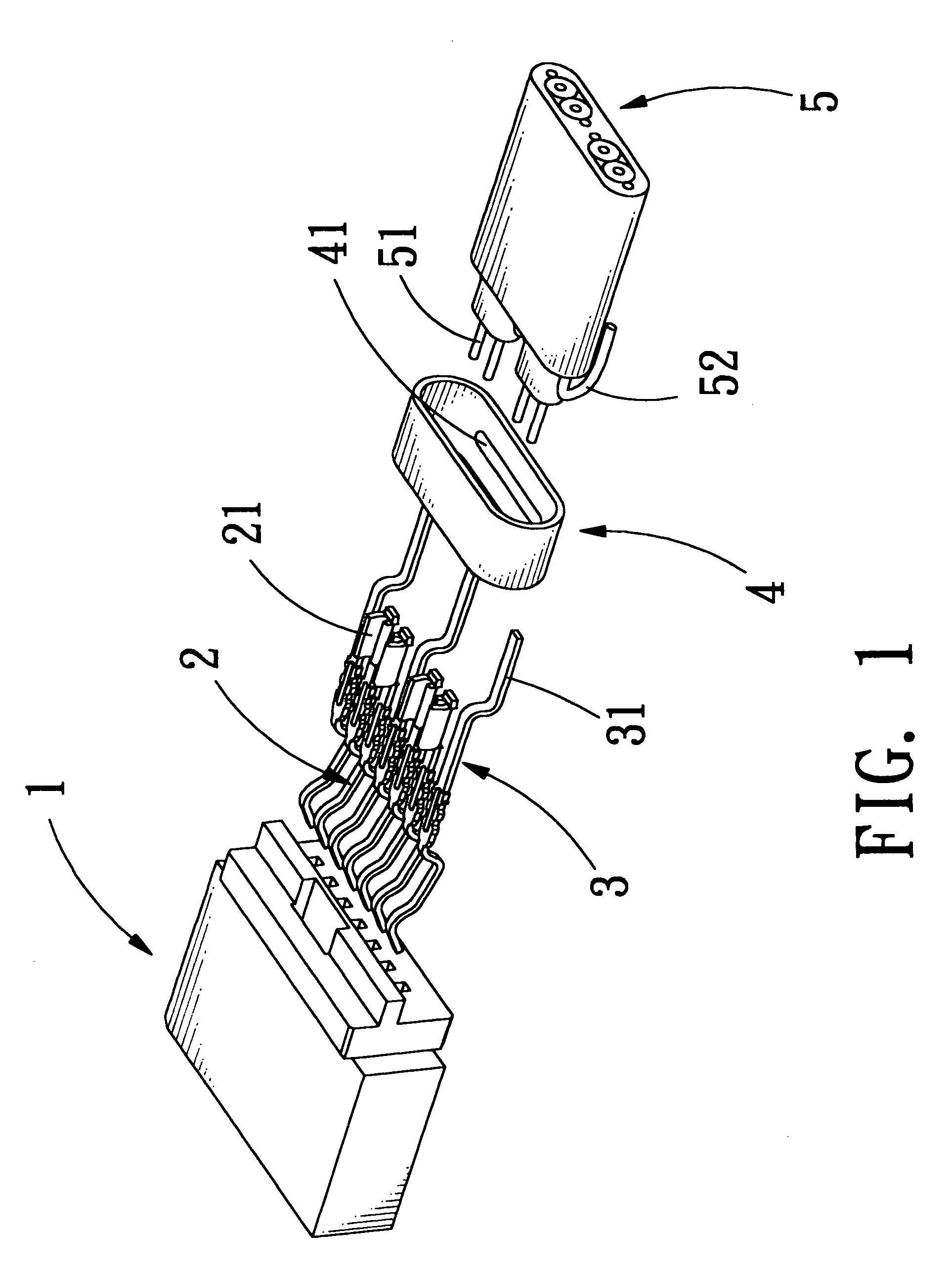
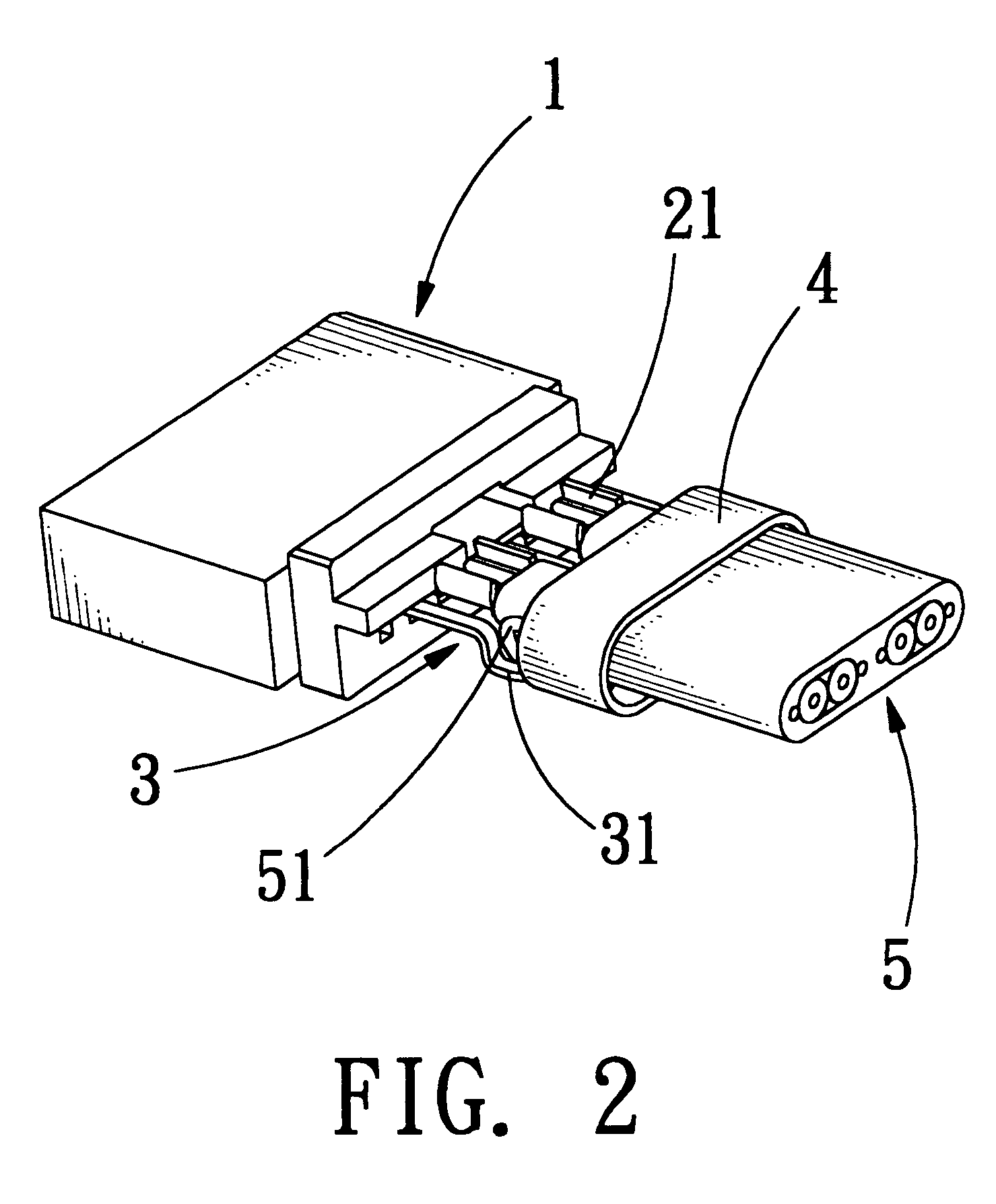
[0013]Referring to FIGS. 1-2, which show the exploded view and assembly view of the grounding structure according to one embodiment of the present invention. As shown in FIGS. 1 and 2, the grounding structure of the present invention mainly comprises: a housing 1; predetermined transmitting terminals 2 and grounding terminals 3 inserted inside the housing 1; a cable 5, comprising a predetermined number transmitting units 51 and grounding lines 52; and a connecting part 4, engaging the grounding terminals 3 with the grounding line 52 to form electrical contact. Each of the plurality of transmitting units having one of the plurality of grounding lines located on each of two opposing sides thereof.

[0014]Wherein, the connecting part 4 is a sheath with electrical contact material, preferably, and it further comprises a protrusion portion 41 installed at the appropriate position to increase the contact effect and the protrusion portion 41 can be formed into a protrusion shape by the press...


PUM


Abstract

The present invention relates to a grounding structure of an electrical connector suitable for high frequency transmitting. The high frequency connector mainly has a connecting part being combined with a plurality of grounding lines to improve the electrical characteristics of the high frequency connector when it transmits a signal. Wherein, the connecting part further comprises a wing portion and a protrusion portion; thereby the connecting part can engage the grounding terminals with the grounding line of the cable to form electrical contact. Furthermore, one end of the connecting part is extended directly and comprises predetermined grounding terminals, such that the grounding line can be directly connected to connecting part; such as, the electrical connector can have better electrical characteristics and the grounding line can directly be coupled to the grounding terminals without the soldering process by using aforesaid structure meanwhile, the entire assembly process and the relative cost can be lessened.

Description

BACKGROUND OF THE INVENTION[0001]1. Field of the Invention[0002]The present invention relates to a grounding structure of an electrical connector suitable for high frequency transmitting. The high frequency connector mainly has a connecting part being combined with a plurality of grounding lines to improve the electrical characteristics of the high frequency connector when it transmits a signal, and the grounding line of the high frequency connector can directly be coupled to the grounding terminals without a soldering process such that the entire assembly process and the relative cost can be lessened.[0003]2. Description of the Related Art[0004]Generally, most grounding structure of the prior art connector used on the motherboard of the computer mainly is soldered directly to the grounding line and the grounding terminals, however, due to the science and technology increasing continuously and the environmental protection sense raising, the assembly process of the electronic industr...

Claims


Application Information

Patent Timeline
Patent Type & Authority Patents(United States)
IPC IPC(8): H01R4/66H01R9/03H01R13/648
CPCH01R13/648H01R9/034H01R13/65914
Inventor HSU, I-CHANGCHOU, FU-CHENCHEN, PI-CHING
Owner ING SHANG LUN
Why Eureka
Try Eureka