

Coil device
a coil and coil technology, applied in the direction of transformer/inductance details, basic electric elements, electrical apparatus, etc., can solve the problems of leakage flux, difficult automation of operation, heat dissipation of coils, etc., and achieve the effect of easy connection of lead parts and low height profiles
- Summary
- Abstract
- Description
- Claims
- Application Information
AI Technical Summary
Benefits of technology
Problems solved by technology
Method used
Image

Examples
first embodiment
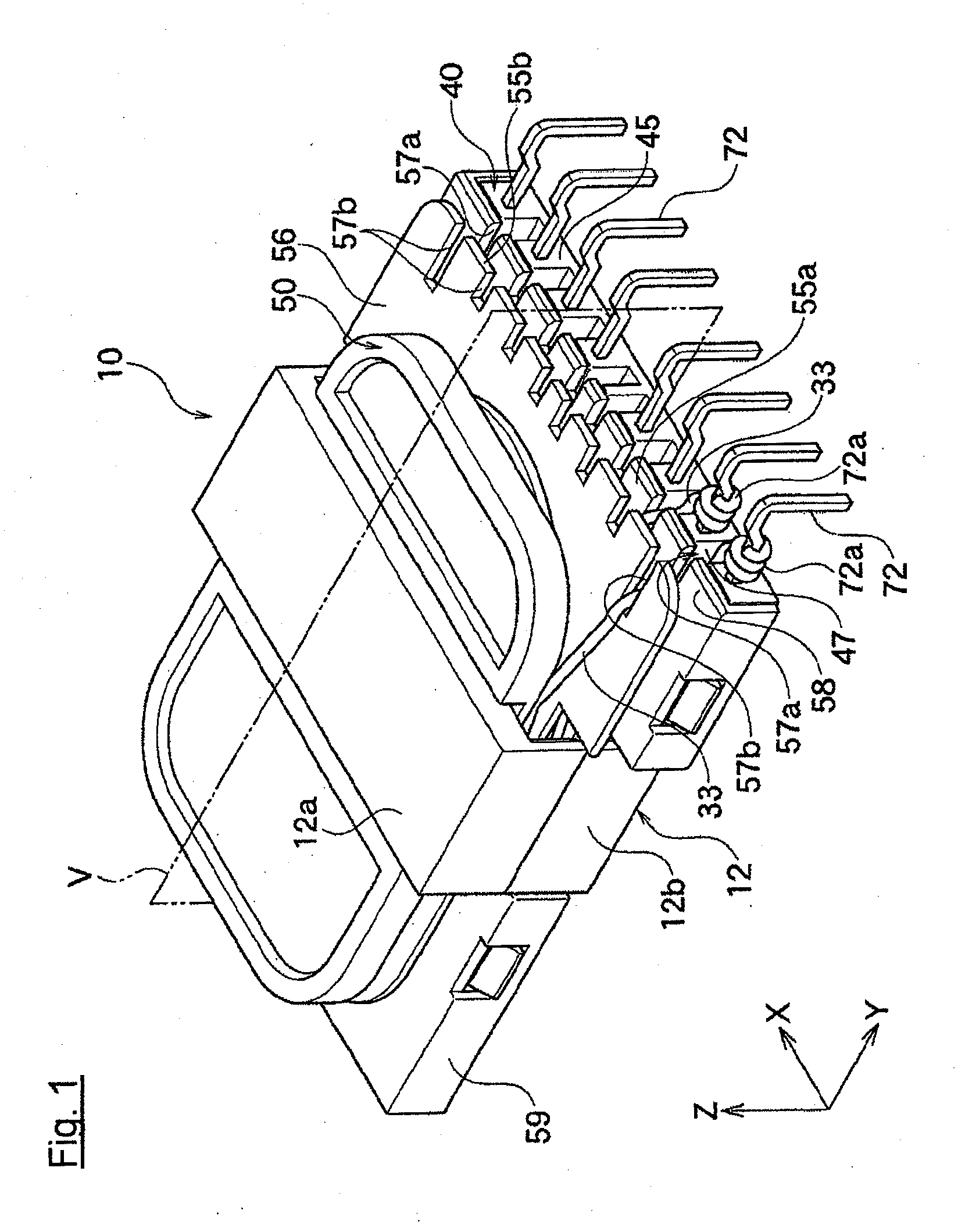
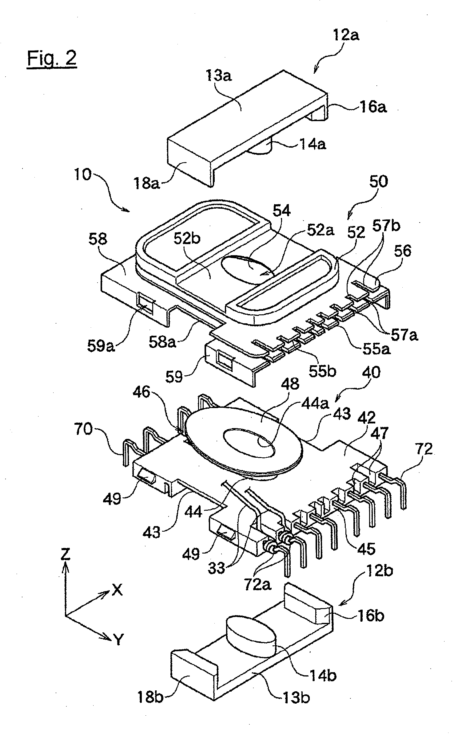
[0049]As shown in FIG. 1, a coil device 10 according to a first embodiment of the present invention comprises a core 12, a bobbin 40 and a case 50.
[0050]The core 12 of the coil device 10 forms a flux path where flux generated from a coil described later passes. It is formed by assembling the first core 12a and the second core 12b, which are separately formed. The first core 12a and the second core 12b have symmetrical shape and they are attached to each other, sandwiching the case 50 and the bobbin 40 from upward and downward directions (Z-axis direction in FIG. 1).
[0051]As shown in FIG. 1, the core 12 comprises the first core 12a and the second core 12b respectively having a generally E-shaped cross-sectional view (cut section including X-axis and Y-axis in FIG. 1). As shown in FIG. 2, each core 12 a and 12b is composed of ferrite cores and comprises planer base portions 13a, 13b extending in the X-axis direction, side legs 16a, 16b, 18a, 18b projecting from both ends of X-axis dir...
second embodiment
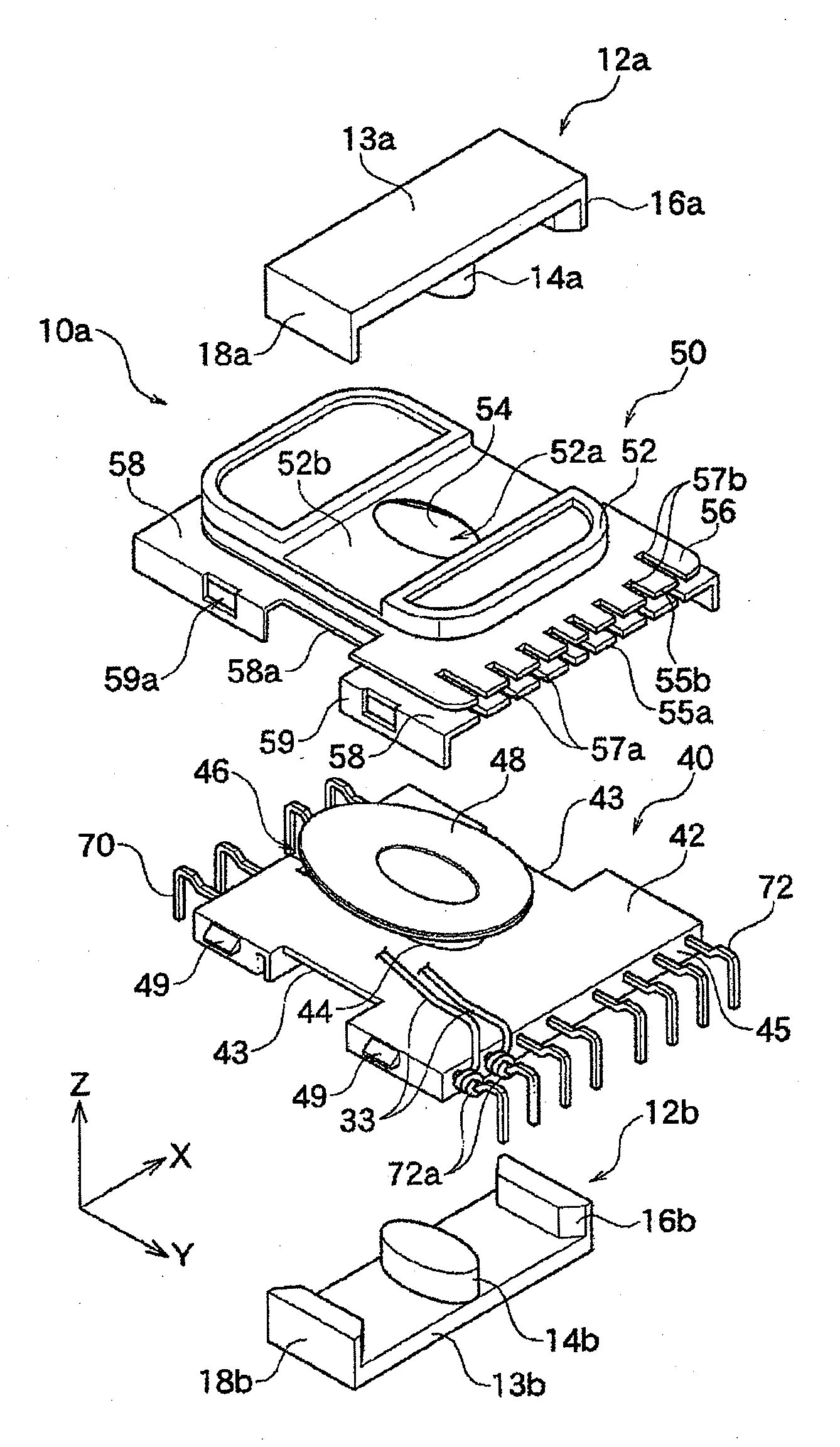
[0095]As shown in FIGS. 8 and 9, in the second embodiment, a coil device 10a is constituted as is the same with the first embodiment, except for the followings. Further, common codes are added to common parts, and the explanation for that is abbreviated.
[0096]In the present embodiment, as shown in FIGS. 8 and 9, a tip end portion 55a of lower collar part 58 of case 50 and a tip end portion 55b of intermediate collar part 56 project in the Y-axis direction, with respect to an end portion 45 of the bobbin plate 40. In this embodiment, first grooves 57a for lead are formed on a tip end portion 45a of the projecting lower collar part 58 and third grooves 57b for lead are formed on a tip end portion 45b of the intermediate groove 56.
[0097]Therefore, in the present embodiment, the process, that an end portion of lead wire 33 winds around a connection part 72a of the secondary terminal 72 by engaging it on the first groove 57a and the third groove 57b for leads, is easy without forming the...
PUM
| Property | Measurement | Unit |
|---|---|---|
| creepage distance D2 | aaaaa | aaaaa |
| outer circumference | aaaaa | aaaaa |
| circumference | aaaaa | aaaaa |
Abstract
Description
Claims
Application Information