Metal fastening die assembly

a technology of metal fastening and die assembly, which is applied in the direction of perforating tools, manufacturing tools, shaping tools, etc., can solve the problems of unfavorable replacement of anvils, difficulty in fastening access, and add undesired extra height, and achieves easy access to workpieces, small lateral size, and low height profile

Active Publication Date: 2021-11-18
BTM COMPANY
View PDF4 Cites 1 Cited by
  • Summary
  • Abstract
  • Description
  • Claims
  • Application Information

AI Technical Summary

Benefits of technology

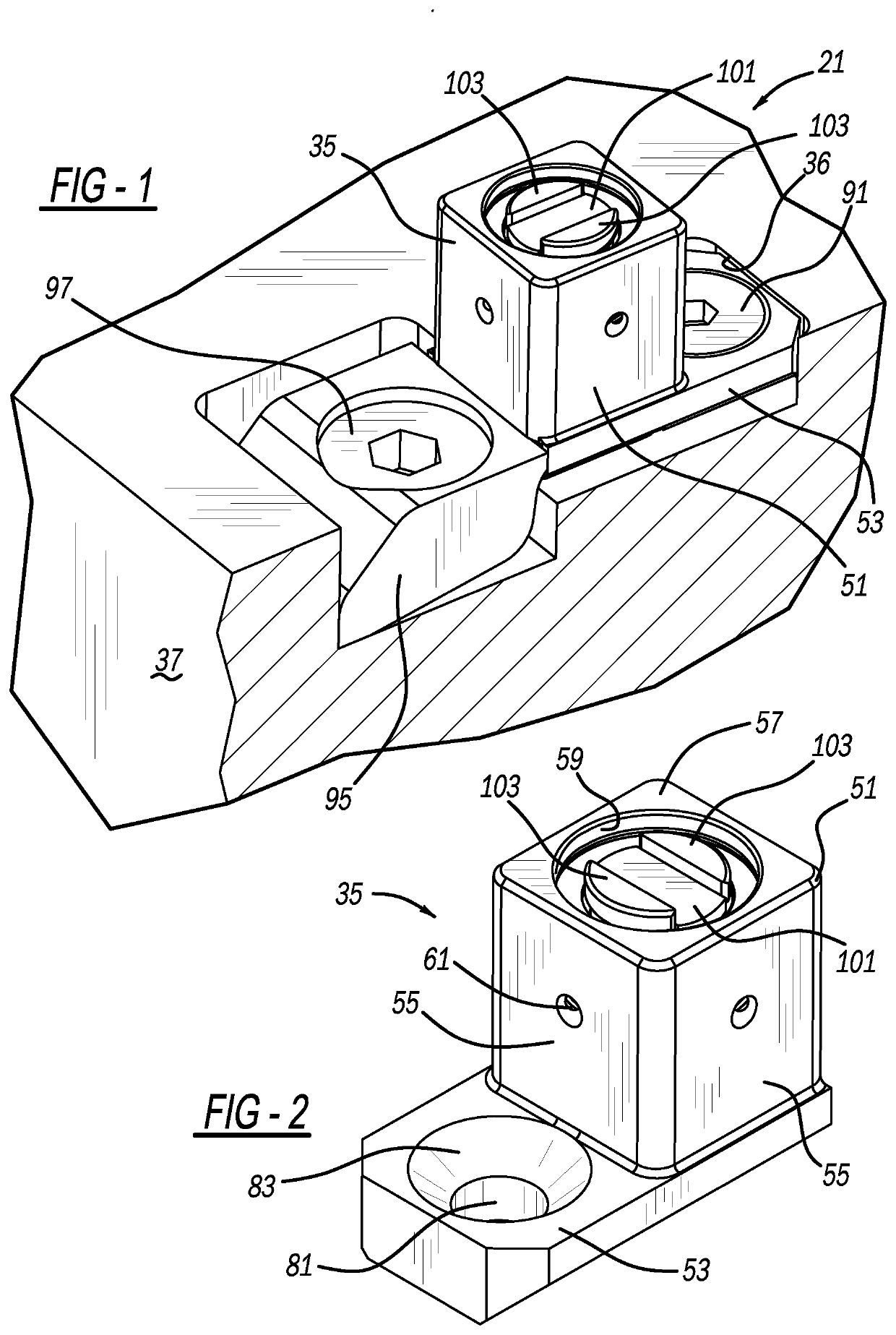
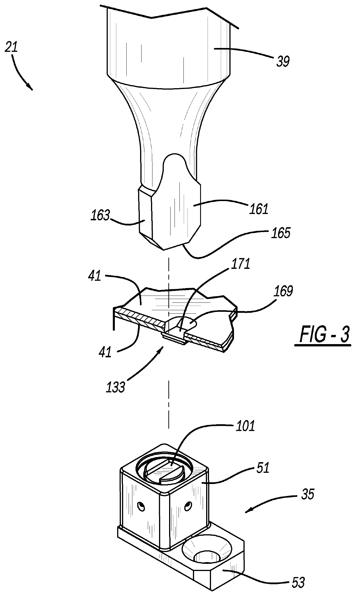
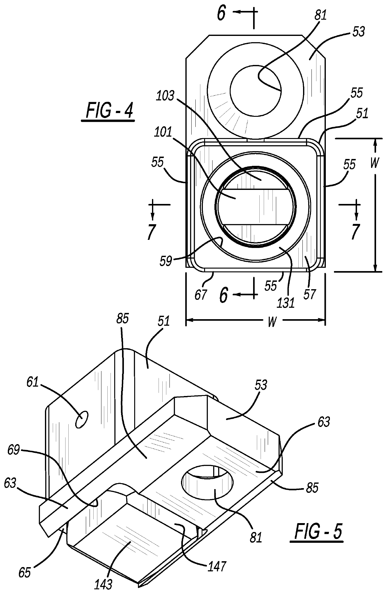
[0006]The present apparatus and method are advantageous over traditional devices. For example, the integral shield and retainer sections reduce separate parts while providing a low height profile and smaller lateral size, to more easily access workpieces. The specific shape of the present die shield beneficially provides a low height profile and smaller lateral size to more easily fasten difficult to access workpieces. Furthermore, the present design makes assembly and disassembly of the die blades and the anvil much easier. Moreover, fewer parts and multi-functionality are beneficially achieved with the present apparatus. The present assembly and method advantageously make it easier and more accurate to reorient a central anvil and / or surrounding die blades, but without the need to reorient the outer die shield and fixture. The single piece and integral nature of the die shield and retainer improve the strength of the die assembly and its mounting, in certain aspects of the present apparatus. Certain component integration and separation in various embodiments allow for the use of different and more durable materials for some parts while reducing expense for other parts; by way of non-limiting example, the integrated anvil and base may be made of a more durable metal than the less expensive metal of the integral die shield and die retainer. Additional advantages and features of the present apparatus and method can be ascertained from the following description and appended claims, taken in conjunction with the accompanying drawings.

Problems solved by technology

While these devices were significant improvements in the industry, the separate external shield of the die assembly in addition to the distinct holder sometimes causes extraneously redundant components and also can add undesired extra height to the combination which may render fastening access difficult when certain workpiece shapes are encountered.
However, the anvil cannot be removed for replacement due to wear during use.

Method used


Image

  • Metal fastening die assembly
  • Metal fastening die assembly
  • Metal fastening die assembly

Examples


first embodiment

[0033]Another embodiment of a die assembly 221 is illustrated in FIGS. 15 and 16. This exemplary embodiment includes a differently shaped die guard having integrally machined die shield 223 and retainer 225 sections with parallel through bores 227 and 229, respectively. Opposite ends of the die shield and retainer sections are laterally curved with straight lateral sides 331 spanning therebetween. A workpiece contacting end 333 is coplanar, flat and at the same height for both the die shield and retainer sections, unlike the stepped shape of the previous embodiments. An anvil 335, die blades 337 and biasing ring 339 are the same as with the first embodiment, however, a base 341 of the anvil differs. The present base 341 has a generally circular and curved peripheral edge 343 which laterally extends wider than an intermediate die body section of the anvil. The laterally outer portion of base 341 fits without a bottom recess 345 of die shield 223, such that a backside surface 347 of t...

fifth embodiment

[0036]Reference should now be made to FIG. 18. A fifth embodiment die assembly 451 includes a die guard having a die shield section 453 and a retainer section 455 machined as a single integral part. This configuration of die shield section 453 employs a circular-cylindrical outer surface 461 longitudinally extending more than twice the height and more preferably at least four times the height of the longitudinal height dimension of the retainer. A concentric circular-cylindrical inner surface of a through bore 465 is also present. Retainer 453 laterally extends from one side of die shield section 453 but not the opposite side, and a tapered backside surface continuously laterally extends under the retainer and die shield sections adjacent an elongated edge. Moveable die blades 459 are biased toward a central anvil 457 by a flexible ring or spring 463 as with the previous embodiments. A laterally enlarged base (with either the polygonal or curved periphery, and with an optional cente...


PUM

PropertyMeasurementUnit
heightaaaaaaaaaa
heightaaaaaaaaaa
heightaaaaaaaaaa

Abstract

A metal fastening or joining apparatus is provided. In another aspect, a single piece die guard includes an integral die shield section and an integral retainer section, wherein a die anvil can be removed, and the die shield section has a low height and a small lateral square width. A further aspect employs a generally square peripheral shape for a die shield within which is an anvil and movable die blades, which are operable to fasten or join sheet metal workpieces together in an interlocking manner. In still another aspect, a projecting and/or peripheral orientation structure is on a backside of a workpiece fastening die assembly which allows for anvil reorientation without the need to also reorient a laterally surrounding die shield and retainer.

Description

BACKGROUND AND SUMMARY[0001]The present disclosure generally pertains to a fastening apparatus and more particularly to a metal fastening die assembly.[0002]It is well known to employ a punch and die assembly to create a clinch joint within sheet metal workpieces located therebetween. Furthermore, many conventional die assemblies are mounted onto separate die retainers or holders in order to secure the die assemblies to a frame of an actuator tool. Examples of such die assemblies and separate holders are disclosed in the following U.S. patents invented by Sawdon which are commonly owned with the present application: U.S. Pat. No. 7,694,399 entitled “Sheet Fastening Apparatus and Method” which issued on Apr. 13, 2010; U.S. Pat. No. 6,430,795 entitled “Composite Urethane Stripper for Metal Joining Apparatus” which issued on Aug. 13, 2002; and U.S. Pat. No. 5,860,315 entitled “Device for Securing Tools” which issued on Jan. 19, 1999. These patents are all incorporated by reference here...

Claims


Application Information

Patent Timeline
Patent Type & Authority Applications(United States)
IPC IPC(8): B21D39/03B21D28/34
CPCB21D39/031B21D45/006B21D28/34B21J15/025B21D37/10B21D37/04Y10T29/49837B21D39/035B21D39/034Y10T29/49833Y10T29/49835
Inventor SPROTBERRY, STEVEN J.FISCH, HANS-WERNER
Owner BTM COMPANY
Why Eureka
Try Eureka