Vertical transformer

a transformer and vertical technology, applied in the direction of transformer/inductance details, basic electric elements, electrical equipment, etc., can solve the problems of difficult suppression of sound by such methods, sound (beat) of transformers occurring while driving, etc., to achieve good durability, reduce height, and reduce noise.

Active Publication Date: 2013-06-06
TDK CORPARATION
View PDF4 Cites 4 Cited by
  • Summary
  • Abstract
  • Description
  • Claims
  • Application Information

AI Technical Summary

Benefits of technology

[0035]Transformer adapting a doubly-structure, wherein one coil is located at inner circumference side of the other coil, is advantageous for low height profile, while bobbin structure tends to be complicated when compared to a transformer of single-structure. As mentioned above, fixed structure according to the present invention shows good durability even with low strength of the first bobbin; this expands the design possibility of material and formation of bobbin within transformer according to the present invention. Therefore, transformer according to the present invention comprising a doubly-structure is possible to reserve superior durability and silence. Further, it is possible to simplify the manufacturing method by adapting set-in structure and the like.

Problems solved by technology

Vertical transformer according to conventional technique is easy to position core with respect to bobbin by locating connection part of magnetic material between the continuing two walls, on the other hand, it had a problem that the sound (beat) of transformer occur when driving.
Namely, fixation methods, including adhering cores to each other, winding tape at outer periphery of transformer, and adhering core and bobbin at their opposing faces, are insufficient for fixing core to bobbin; and that it is difficult to suppress sounds by such methods.

Method used


Image

  • Vertical transformer
  • Vertical transformer
  • Vertical transformer

Examples


second embodiment

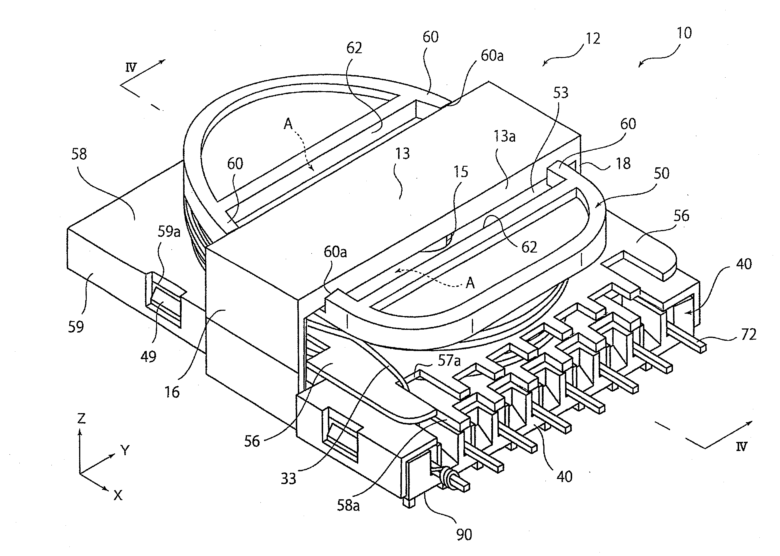
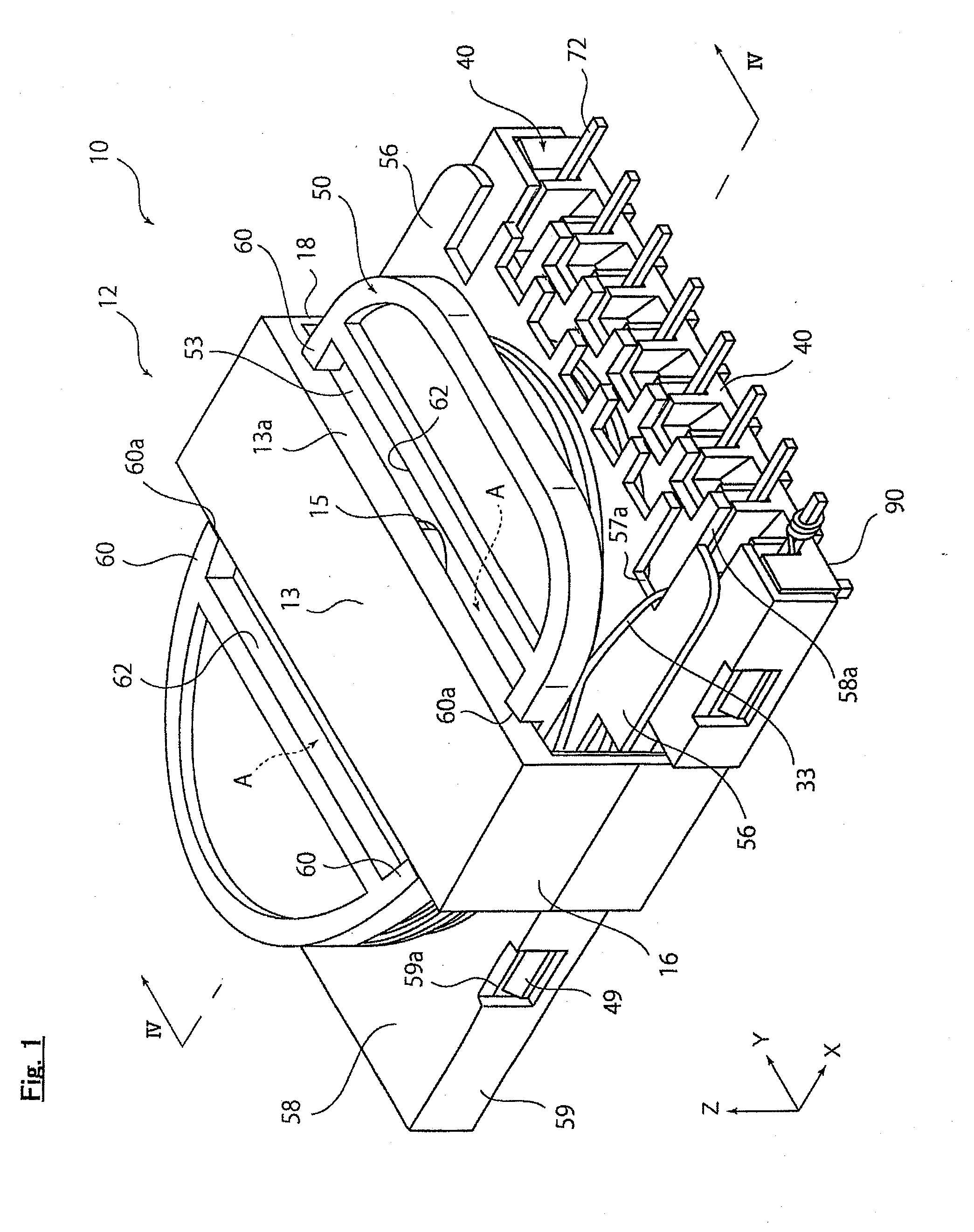
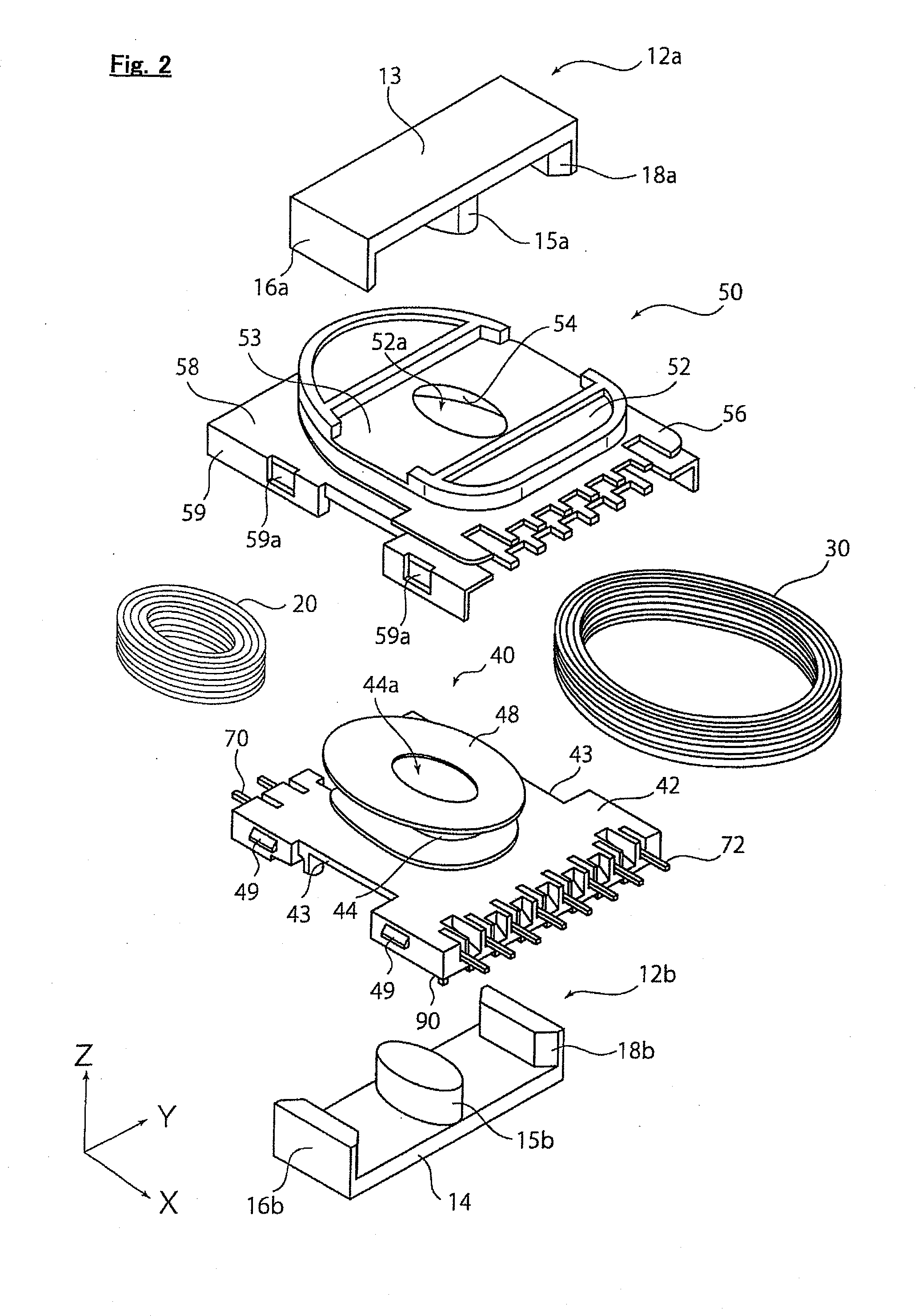
[0088]Transformer 10d according to the second embodiment of the present invention will be described referring to FIGS. 5 to 10. Note that transformer 10d according to the second embodiment is the same with transformer 10 according to the first embodiment, except for formation of the first bobbin 50 and the like. Common codes are added to common parts, and the explanation for that is abbreviated.

[0089]As shown in FIGS. 5 and 6, the first connection part 13 of core 12 extends approximately parallel to a direction parallel to mounting surface 90 and to the second direction connecting middle leg 15 and side legs 16, 18. And the first connection part 13 connects one end portion of middle leg 15 and one end portions of side legs 16, 18. On the other hand, the second connection part 14 of core 12 extends approximately parallel to Y-axis direction and connects the other end portion of middle leg 15 and the other end portions of side legs 16, 18, as is the same with the first connection part...


PUM

PropertyMeasurementUnit
inner circumferenceaaaaaaaaaa
voltageaaaaaaaaaa
magneticaaaaaaaaaa

Abstract

A vertical transformer comprising a core provided with a middle leg installing a first and a second coils, a side leg, a first connection part connecting an end of the middle leg and that of the side leg, and a second connection part connecting the other end of the middle leg and that of the side leg, a first bobbin provided with a first hollow cylinder where at least either the first or the second coil is wound, and a core on-board face connected to an end of the first hollow cylinder, and an adhesive hardened part connecting a connection side face, and the core on-board face, and formed by hardening an adhesion, wherein the core on-board face is provided with a positioning part positioning the connection side face, and a positioning projection, is formed on both sides of the first connection part.

Description

BACKGROUND OF THE INVENTION[0001]1. Field of the Invention[0002]The present invention relates to a vertical transformer used for electrical products and the like.[0003]2. Description of the Related Art[0004]Transformer is used in various electrical products for various uses. For instance, when driving a backlight of liquid crystal display, an inverter resonance transformer is used to obtain a high-voltage.[0005]Note that transformer comprises a horizontal transformer, wherein a leg of core installing coil extends approximately parallel to mounting surface of transformer, and a vertical transformer, wherein a leg of coil installing core extends approximately perpendicular (normal direction of mounting surface) to mounting surface of transformer. For instance, vertical transformer of a conventional technique described such as in Japanese non-examined patent application No. S61-81612 (Patent Article 1) had a structure where 2 walls, continuing from one end to the other end and parallel...

Claims


Application Information

Patent Timeline
Patent Type & Authority Applications(United States)
IPC IPC(8): H01F3/00
CPCH01F27/306H01F3/00
Inventor MAEDA, HIROSHIHONMA, TORU
Owner TDK CORPARATION
Why Eureka
Try Eureka