Position control device, disk device, and position control method

a technology of position control device and disk device, which is applied in the direction of magnetic recording, data recording, instruments, etc., can solve the problems of eccentricity, current position cannot be demodulated correctly, and become a hindrance to such positioning

Inactive Publication Date: 2008-10-07
KK TOSHIBA
View PDF6 Cites 0 Cited by
  • Summary
  • Abstract
  • Description
  • Claims
  • Application Information

AI Technical Summary

Benefits of technology

[0008]The present invention has been designed in consideration of the problem described above, and it is an object of the present invention to provide a position control device, a disk device, and a position control method with which positioning in a target position can be performed without expending time on a seek operation even when virtual circular control is performed using an eccentric disk.
[0018]The present invention provides a disk device, a control device, and a positioning control method with which positioning in a target position can be performed without expending time on a seek operation even when virtual circular control is performed using an eccentric disk.

Problems solved by technology

Eccentricity caused by a discrepancy between the center of servo signals recorded concentrically on the disk and the rotary center of a motor may become a hindrance to such positioning.
When a servo signal is recorded on the disk by an external device using a media servo track writing (STW) method or the like, and the servo signal is read by loading the disk into the disk device, eccentricity occurs if the rotary center of the external device disk and the rotary center of the disk device do not match.
However, even when virtual circular control is performed, the current position cannot be demodulated correctly when the relative velocity of the eccentric orbit and the virtual circular orbit (the orbit of the head) equals or exceeds a certain value.
Hence, the head cannot be positioned accurately in a target position, and a seek operation takes a great deal of time.

Method used


Image

  • Position control device, disk device, and position control method
  • Position control device, disk device, and position control method
  • Position control device, disk device, and position control method

Examples


Embodiment Construction

[0038]A preferred embodiment of the present invention will be described below with reference to the drawings.

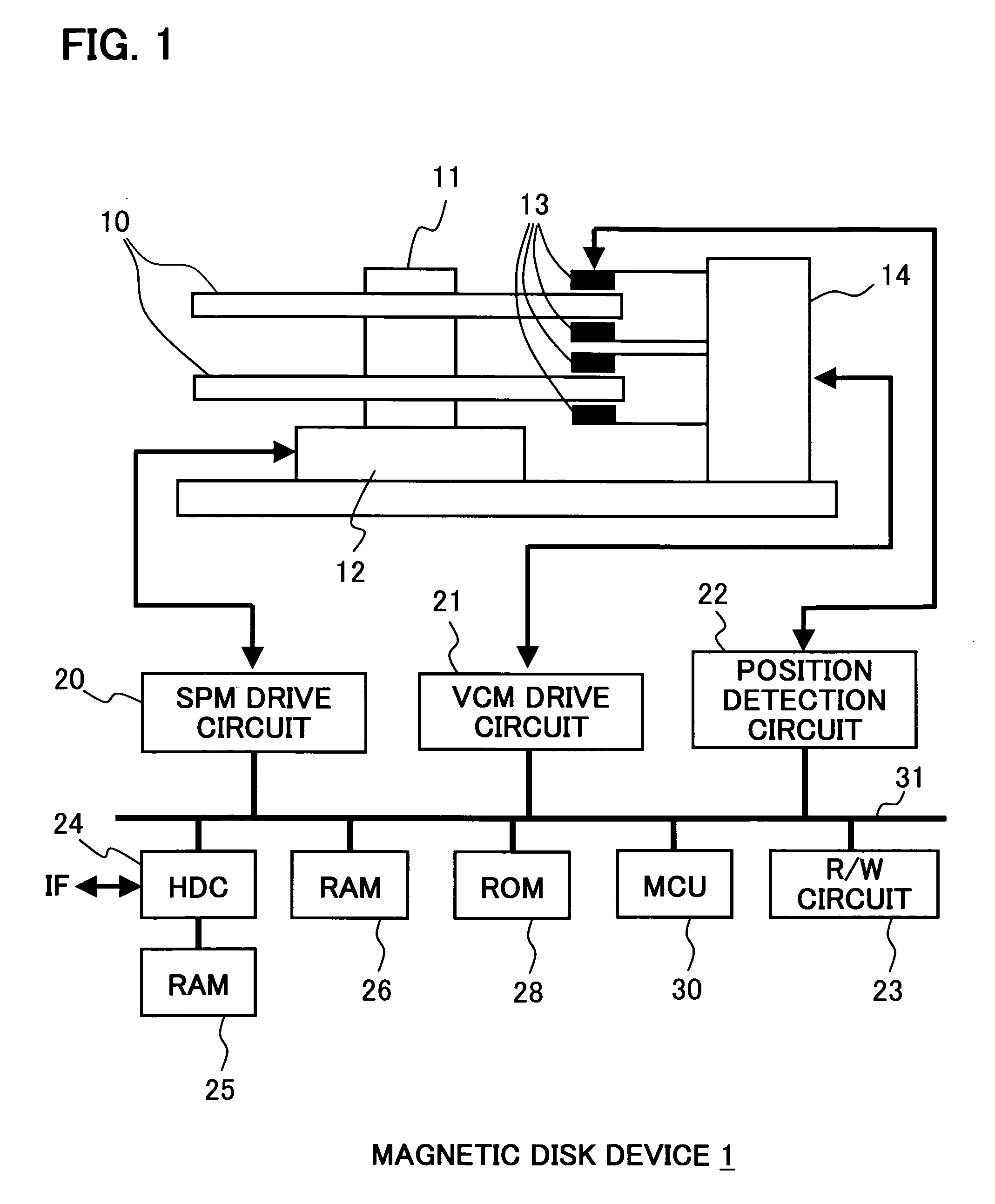
[0039]FIG. 1 shows a configuration example of a magnetic disk device to which the present invention is applied. A hard disk drive is used as an example of the disk device.

[0040]As shown in FIG. 1, the magnetic disk device 1 has a magnetic disk 10, a spindle motor 12, a magnetic head 13, and an actuator 14.

[0041]The magnetic disk 10 is disposed on a rotation axis 11 of the spindle motor 12. The spindle motor 12 rotates the magnetic disk 10 via the rotation axis 11.

[0042]The magnetic head 13 is comprised of read elements and write elements, and reads data from and writes data to the magnetic disk 10.

[0043]The actuator 14 is comprised of a voice coil motor (VCM), which rotates with an internal rotation axis as the center. The actuator 14 also has the magnetic head 13 on a tip end thereof, and is capable of moving the magnetic head 13 in the radial direction of the magnetic disk ...


PUM

PropertyMeasurementUnit
relative velocityaaaaaaaaaa
speedaaaaaaaaaa
velocityaaaaaaaaaa

Abstract

The present invention provides a disk device, a control device, and a positioning control method with which positioning in a target position can be performed without expending time on a seek operation even when virtual circular control is performed using an eccentric disk. Virtual circular orbits, each depicting a perfect circle centered on the rotary center of a disk surface, are determined. An average orbit is then determined by averaging the virtual circular orbits. Orbits obtained by subtracting the average orbit from each virtual circular orbit are set as the position orbits of the respective disk surfaces. An MCU controls an actuator to follow these orbits.

Description

CROSS-REFERENCE TO RELATED APPLICATIONS[0001]This application is based upon and claims the benefit of priority from the prior Japanese Patent Application No. 2006-057203, filed on Mar. 3, 2006, the entire contents of which are incorporated herein by reference.BACKGROUND OF THE INVENTION1. Field of the Invention[0002]The present invention relates to a disk device, a position control device for positioning a head of the disk device in a target position, and a position control method. More particularly, the present invention relates to a disk device and so on with which the head of the disk device can be positioned in the target position without expending time on a seek operation even when an eccentric disk is used.2. Description of the Related Art[0003]With a disk device for a disk such as an optical disk or magnetic disk, it is extremely important to position the head in a target position accurately. Eccentricity caused by a discrepancy between the center of servo signals recorded co...

Claims


Application Information

Patent Timeline
Patent Type & Authority Patents(United States)
IPC IPC(8): G11B5/596G11B21/02
CPCG11B5/59627
Inventor TAKAISHI, KAZUHIKO
Owner KK TOSHIBA
Why Eureka
Try Eureka