Dust containment apparatus for drywall sanding

Inactive Publication Date: 2006-09-12
TERRY MARK E
View PDF7 Cites 6 Cited by
  • Summary
  • Abstract
  • Description
  • Claims
  • Application Information

AI Technical Summary

Benefits of technology

[0008]It is an object of the present invention, therefore, to provide a new and improve

Problems solved by technology

Whether the sanding takes place during residential or commercial construction, remodeling or rehabilitation, the problem of drywall spackle dust has been both a cosmetic and health p

Method used


Image

  • Dust containment apparatus for drywall sanding
  • Dust containment apparatus for drywall sanding
  • Dust containment apparatus for drywall sanding

Examples


Embodiment Construction

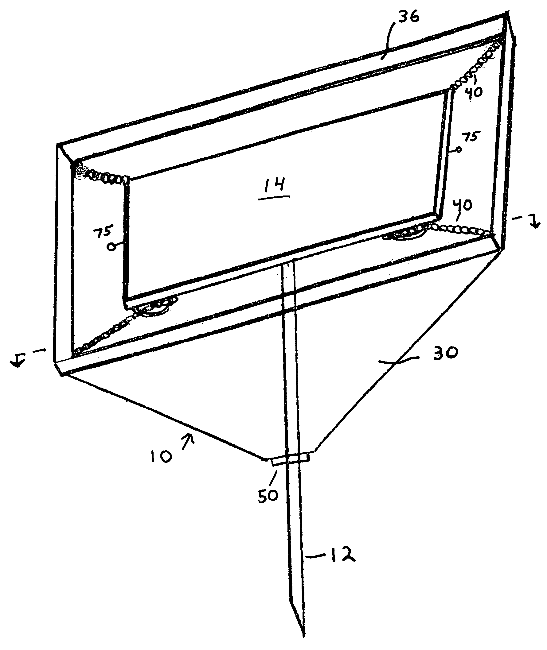
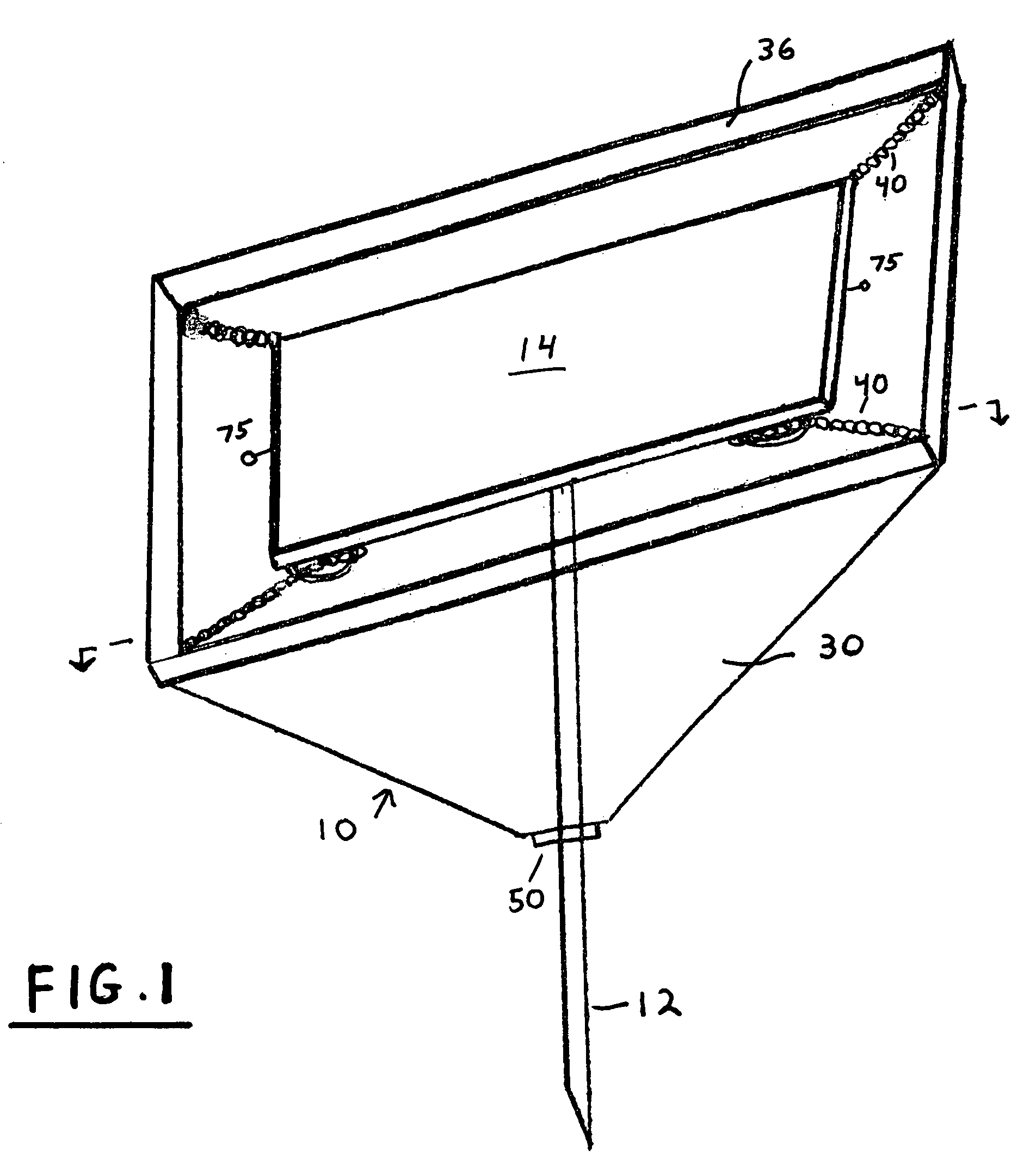
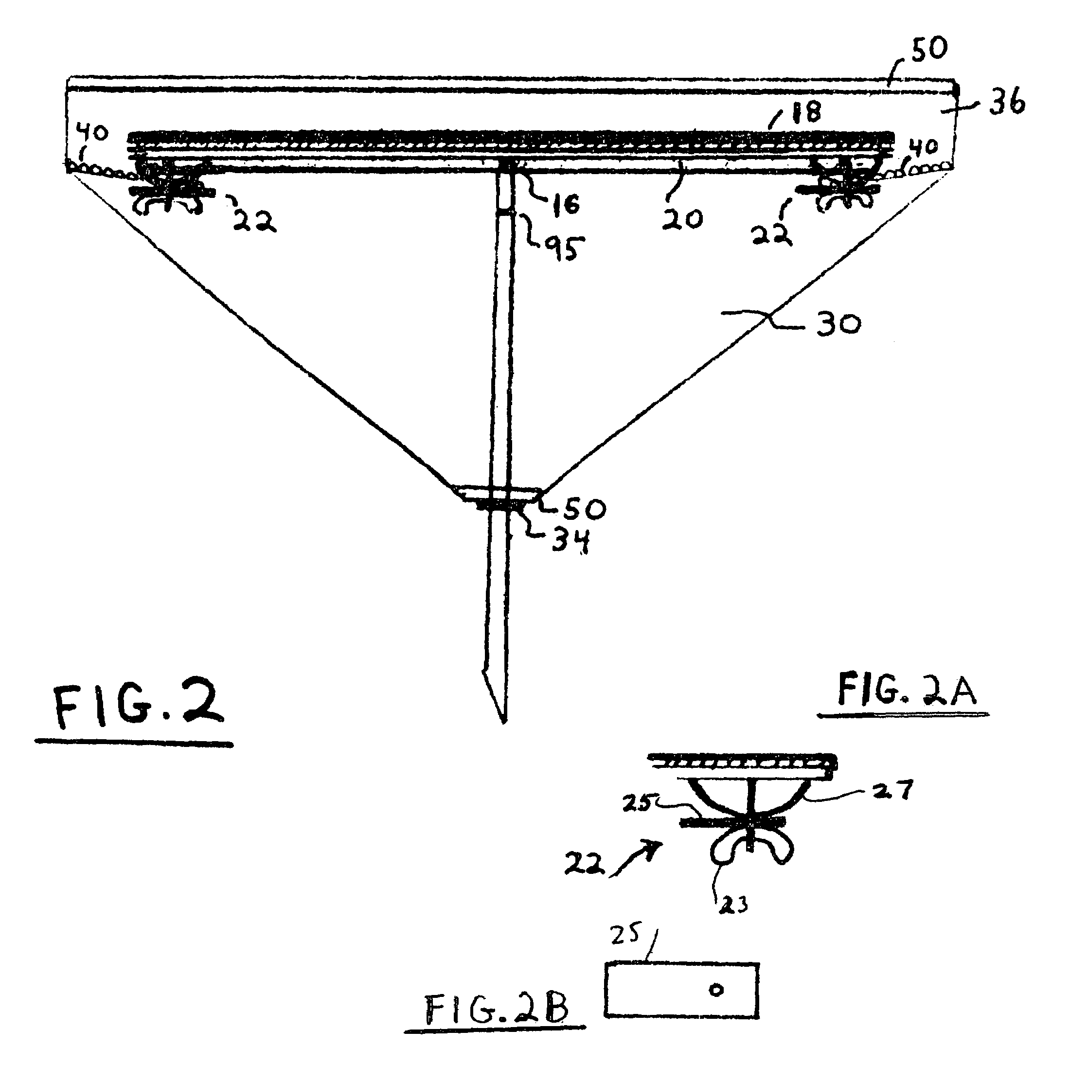
[0023]In the drawings, the drywall sanding apparatus 10 includes a drywall sanding pole 12 having a sanding component 14 adjustable left-and-right, forward-and-back about a swivel 16. With the component 14 having a sanding surface 18 and an underside 20, the apparatus of the invention includes a pair of clamps (or like holding devices) 22 secured at the underside 20 of the sanding component 14. Four such clamps are illustrated in the configuration of FIG. 1 for a rectangular configuration of the sanding component 14, although the operation of the present invention will operate in the manner to be described with only a single such pair of clamps provided, as at 75 in FIG. 1. The drywall sanding apparatus 10 then incorporates a collecting bag 30 having an open top 32 (FIG. 5) and an apertured bottom 34 (FIGS. 3–5), with the open top 32 being joined with a frame 36 whose dimensions are greater than that of the sanding component 14. Two pairs of expandable springs 40 are permanently sec...


PUM


Abstract

Drywall sanding apparatus employing a spring tensioned frame surround about its sanding component to capture substantially all generated dust within a collecting bag secured with said frame, to be thereafter emptied.

Description

CROSS-REFERENCE TO RELATED APPLICATIONS[0001]NONESTATEMENT REGARDING FEDERALLY SPONSORED RESEARCH OR DEVELOPMENT[0002]Research and development of this invention and Application have not been federally sponsored, and no rights are given under any Federal program.REFERENCE TO A MICROFICHE APPENDIX[0003]NOT APPLICABLEBACKGROUND OF THE INVENTION[0004]1. Field of the Invention[0005]This invention relates to the sanding of drywalls, in general, and to the collection and containment of spackle compound dust generated thereby, in particular.[0006]2. Description of the Related Art[0007]As will be appreciated, a major concern in the drywall sanding of walls and ceilings is the generation and collection of airborne created spackle compound dust. Whether the sanding takes place during residential or commercial construction, remodeling or rehabilitation, the problem of drywall spackle dust has been both a cosmetic and health problem for some time. Power sanders with vacuum and hose attachments h...

Claims


Application Information

Patent Timeline
IPC IPC(8): B24B27/08B24D15/00
CPCB24D15/023B24B55/10
Inventor TERRY, MARK E.
Owner TERRY MARK E
Why Eureka
Try Eureka