System and method for input current shaping in a power converter

Inactive Publication Date: 2008-10-07
DIALOG SEMICONDUCTOR INC
View PDF43 Cites 40 Cited by
  • Summary
  • Abstract
  • Description
  • Claims
  • Application Information

AI Technical Summary

Benefits of technology

[0012]The power converter of the present invention and the method for controlling the power converter can transfer electrical power from a power source to a load with a high power factor over a wide range of input voltage with the input current shaped by the reference shape of peak current. Peak current switching ensures that the peak input current to the power converter does not exceed the peak current values prescribed for the corresponding phase of the input voltage to the power converter according to the reference shape of peak current, and thus the shape of the input current is determined by the reference shape. The power converter and the method for controlling the power converter of the present invention are compatible with different topologies of power converters, including flyback power converters and boost-type power converters, providing an input current shaped by the reference waveform, to achieve regulation of output voltage with high power factor over a wide range of input voltage.

Problems solved by technology

These conventional power converters may work well in a given range of input voltage levels, but none of these conventional power converters can deliver electrical power with high power factors over a broad or full range of input voltage.
The implementation of these conventional power converters requires complex circuitry further requiring considerable efforts to stabilize them.
Furthermore, the conventional power converters have a particular topology, but none of the control strategy for these conventional power converters may be used with different topologies of power converters.

Method used


Image

  • System and method for input current shaping in a power converter
  • System and method for input current shaping in a power converter
  • System and method for input current shaping in a power converter

Examples


Embodiment Construction

[0033]The embodiments of the present invention will be described below with reference to the accompanying drawings. Like reference numerals are used for like elements in the accompanying drawings.

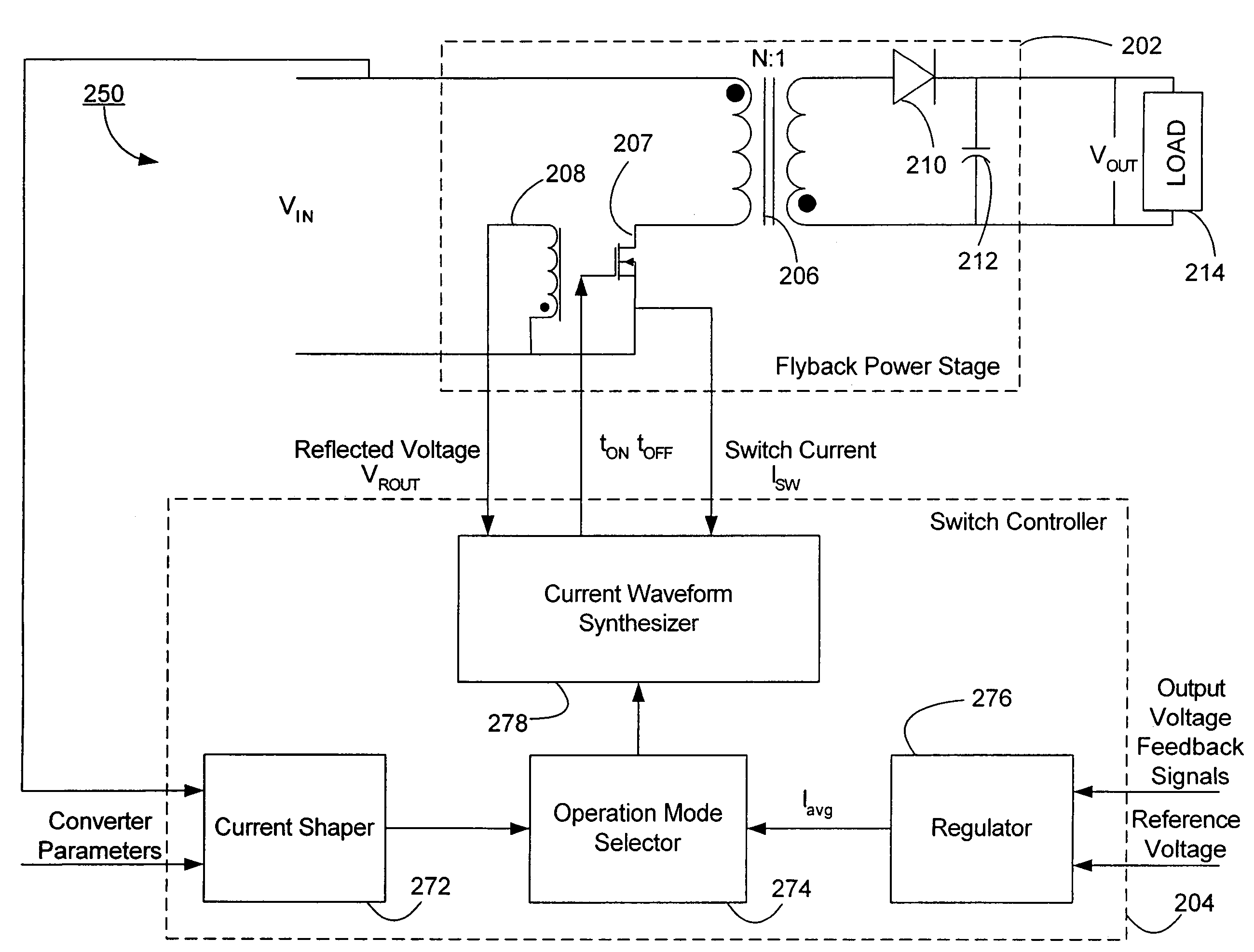
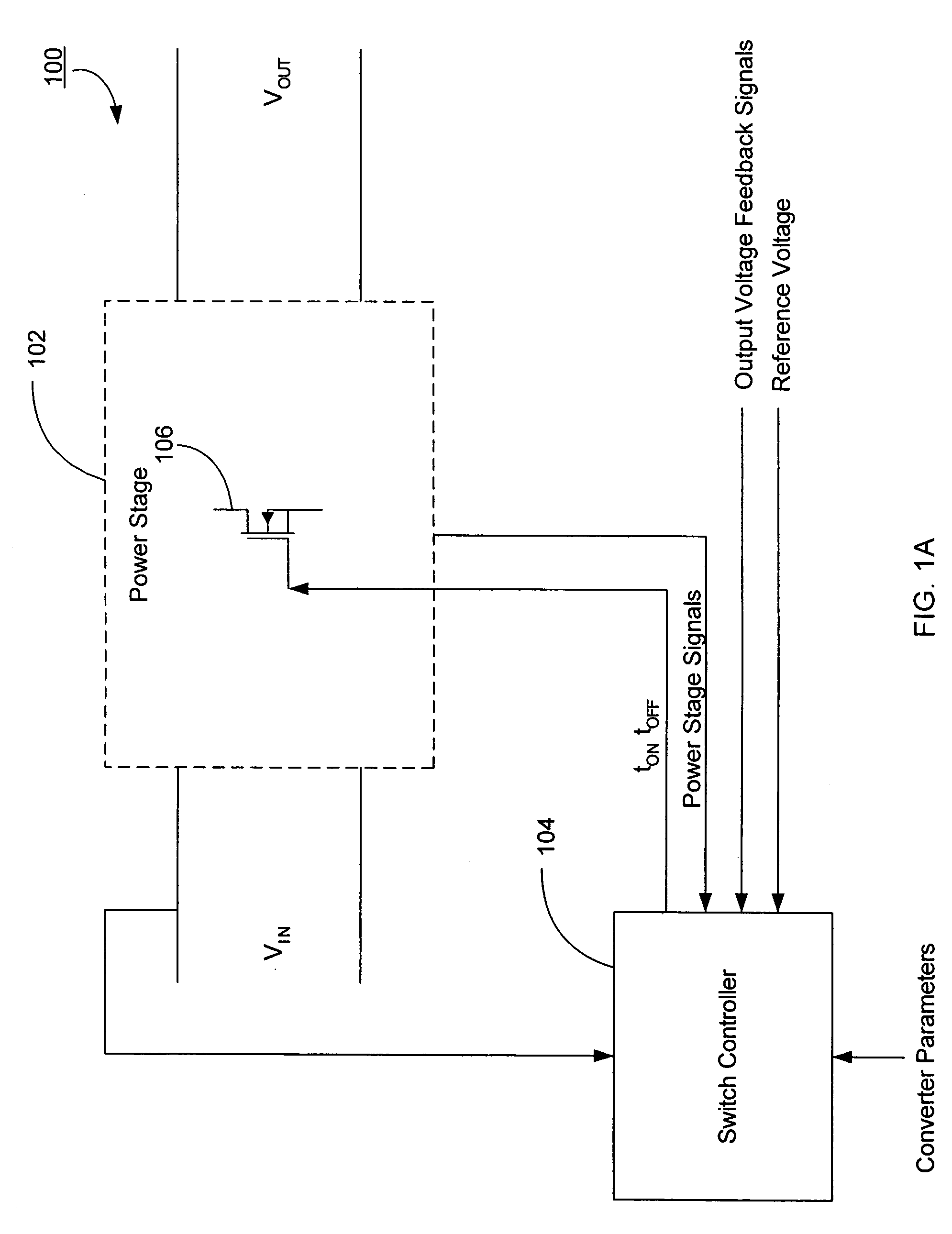
[0034]FIG. 1A is a diagram of the power converter 100 according to one embodiment of the present invention. The power converter 100 includes a power stage 102 and a switch controller 104. The power stage 102 receives full-wave rectified input voltage VIN from an electrical power source (not shown) and transfers power to a load (not shown) with an output voltage VOUT by turning the switch 106 on and off to couple or decouple the input voltage VIN to or from the output. The switch 106 is a conventional MOSFET switch but any other type of switch or any number of switches may be used.

[0035]The switch controller 104 generates pulses to open or close the switch 106 so that the power stage 102 can deliver electrical power with high power factor, e.g., 0.90 or more. In one embodiment, the switch co...


PUM


Abstract

A power converter delivers electrical power from an electrical power source to a load according to a plurality of operation modes, where at least one of the operation modes is a peak current switching mode. Under the peak current switching mode, a switch controller controls the switch in the power converter to be kept on until the current through the switch reaches a peak current value corresponding to a given phase of the input voltage signal to the power converter. The peak current values have a reference shape, which may be a trapezoidal. The power converter may have any topology, such as a flyback-type power converter or a boost-type power converter.

Description

CROSS-REFERENCE TO RELATED APPLICATIONS[0001]This application is a continuation-in-part application of, and claims priority under 35 U.S.C. §120 from, co-pending U.S. patent application Ser. No. 10 / 610,977, entitled “System and Method for Input Current Shaping In a Power Converter,” filed on Jun. 30, 2003 now U.S. Pat. No. 6,944,034, the subject matter of which is incorporated by reference herein in its entirety.TECHNICAL FIELD[0002]The present invention relates generally to a power converter, and more specifically, to a system and method for input current shaping in off-line power supplies.BACKGROUND OF THE INVENTION[0003]Shaping input current in power supplies to have a waveform close to a sinusoidal waveform has the potential of reducing or eliminating undesirable harmonics and of increasing power factor. Power factor in power converters is defined as the ratio of the real power delivered to the load to the apparent power provided by the power source. Regardless of what topology ...

Claims


Application Information

Patent Timeline
IPC IPC(8): H02M3/335
CPCH02M1/4225H02M1/4258Y02B70/126Y02B70/10
Inventor COLLMEYER, ARTHUR J.SHTEYNBERG, ANATOLYZHENG, JUNJIEKING, PAUL F.WONG, DICKSON T.RODRIGUEZ, HARRY
Owner DIALOG SEMICONDUCTOR INC
Why Eureka
Try Eureka