Wireless communications device providing enhanced block equalization and related methods

a communication device and block equalization technology, applied in the field of wireless communications systems, can solve the problems of significant complexity reduction, significant computing overhead, and incorrect interpreting of transmitted symbols at the receiving device, and achieve the effect of enhancing block equalization and related methods

Active Publication Date: 2008-10-07
HARRIS GLOBAL COMM INC
View PDF12 Cites 5 Cited by
  • Summary
  • Abstract
  • Description
  • Claims
  • Application Information

AI Technical Summary

Benefits of technology

[0008]In view of the foregoing background, it is therefore an object of the present invention to provide a wireless communications device which provides enhanced block equalization and related methods.

Problems solved by technology

As a result, the channel experiences distortion which can cause transmitted symbols to be incorrectly interpreted at the receiving device.
In an article entitled “A Novel Block Equalization Design for Wireless Communication with ISI and Rayleigh Fading Channels” by Hwang et al., the authors note that a drawback of symbol based equalization is that it requires considerable computing overheads for updating the coefficients on a symbol-by-symbol basis.
On the other hand, Hwang et al. point out that while block equalization may result in a significant decrease in complexity for performing coefficient updates, this approach requires some knowledge of the channel, which generally requires channel estimation.
While this approach is fairly straightforward, it may not provide desired performance when faced with significant fading and interference, and it may also result in relatively high peak-to-average ratios in some circumstances.
While this approach may have certain advantages, it requires significant complexity (especially for wider bandwidths).
Also, relatively high bits / Hz ratios may not be achievable in certain applications.

Method used


Image

  • Wireless communications device providing enhanced block equalization and related methods
  • Wireless communications device providing enhanced block equalization and related methods
  • Wireless communications device providing enhanced block equalization and related methods

Examples


Embodiment Construction

[0021]The present invention will now be described more fully hereinafter with reference to the accompanying drawings, in which preferred embodiments of the invention are shown. This invention may, however, be embodied in many different forms and should not be construed as limited to the embodiments set forth herein. Rather, these embodiments are provided so that this disclosure will be thorough and complete, and will fully convey the scope of the invention to those skilled in the art. Like numbers refer to like elements throughout, and prime and multiple prime notation are used to indicate similar elements in alternate embodiments.

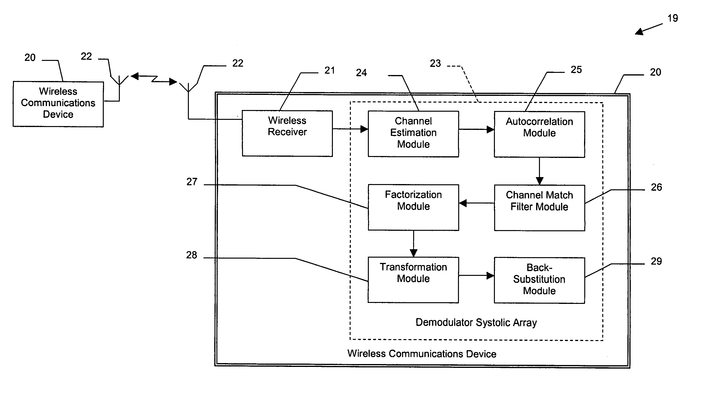
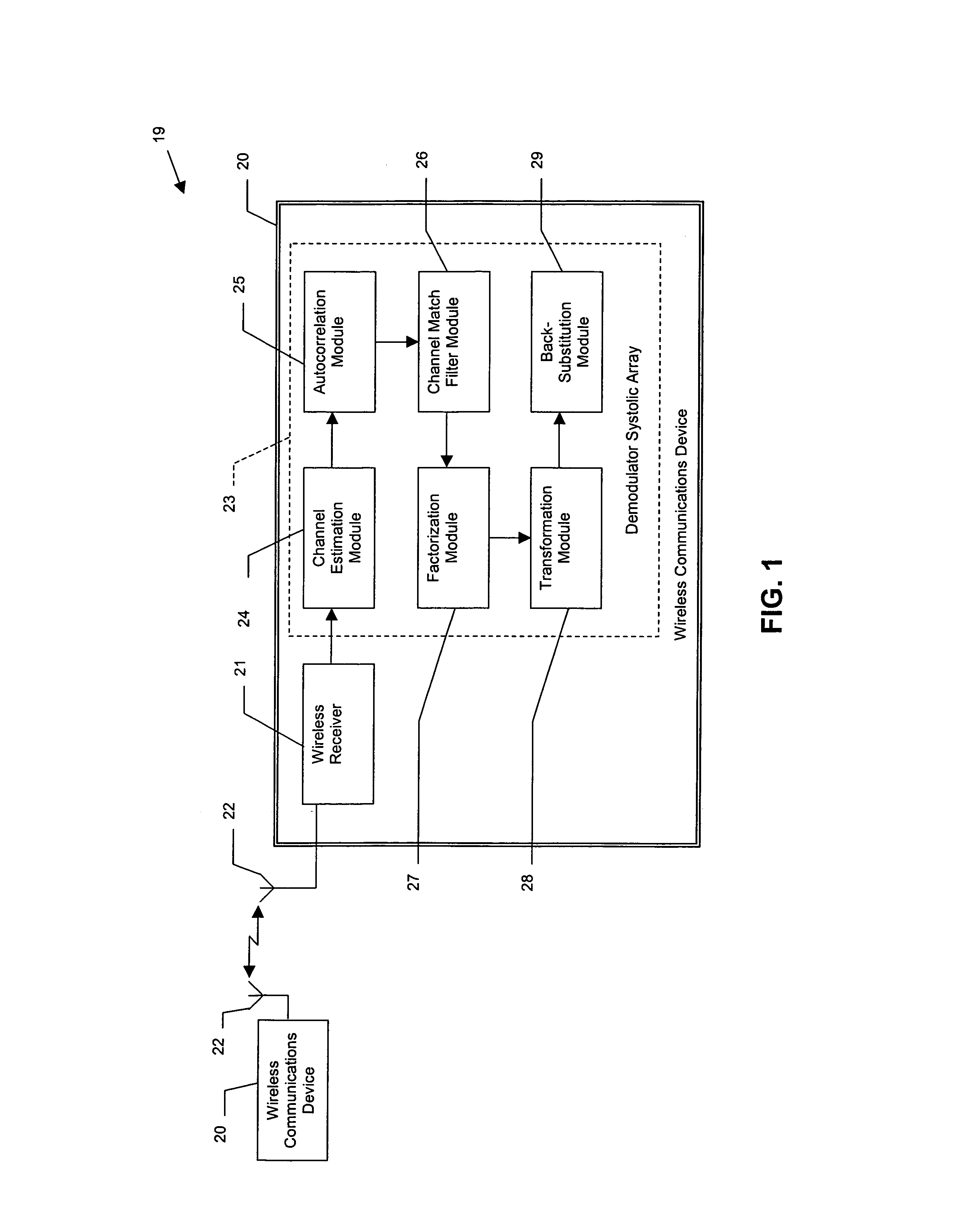
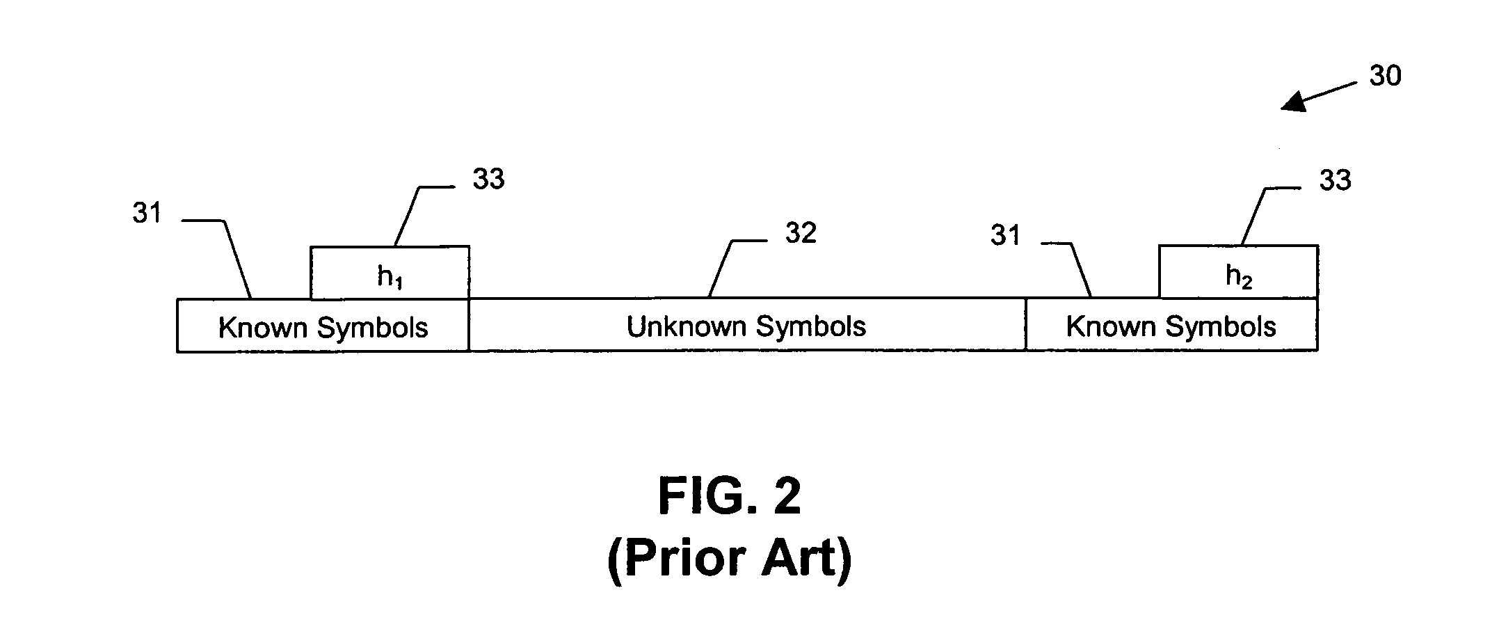
[0022]The present invention is applicable to communication systems in general, but it is particularly concerned with communication systems which insert known sequences in a transmit (TX) waveform to track multi-path and / or fading communication channels (e.g., wireless communications, telephone lines, etc.), and to equalize the received (RX) waveform to rem...


PUM


Abstract

A wireless communications device may include a wireless receiver receiving signals having alternating known and unknown symbol portions over a channel, and a demodulator systolic array. The demodulator systolic array may include a channel estimation module generating respective channel estimates for each unknown symbol portion based upon the known symbol portions. An autocorrelation module may generate autocorrelation matrices based upon the channel estimates. A channel match filter module may generate respective channel matching coefficients for the unknown symbol portions, and a factorization module may divide the autocorrelation matrices into respective upper and lower autocorrelation matrices. A transformation module may transform the channel matching coefficients into upper and lower channel matching coefficients. A back-substitution module may determine the unknown symbol portions by estimating the unknown symbol portions based upon autocorrelation matrices and channel matching coefficients, lower autocorrelation matrices and channel matching coefficients, and combining the estimates.

Description

FIELD OF THE INVENTION[0001]The present invention relates to the field of wireless communications systems, and, more particularly, to wireless communications devices employing block-based channel equalization and related methods.BACKGROUND OF THE INVENTION[0002]High frequency (HF) radio channels, very-high frequency (VHF) radio channels and ultra-high frequency (UHF) radio channels all exhibit time and frequency dispersion (i.e., delay spread and Doppler spread) due to the presence of signal reflectors or scatterers in the environment, as well as the relative motion of transmitters and receivers. As a result, the channel experiences distortion which can cause transmitted symbols to be incorrectly interpreted at the receiving device. Doppler spreading can cause the delay spread (i.e., multipath) to vary with time. These phenomena typically require modems to employ equalization to track and compensate for the time-varying multipath channel.[0003]Two general approaches for channel equa...

Claims


Application Information

Patent Timeline
Patent Type & Authority Patents(United States)
IPC IPC(8): H03D1/00
CPCH04L25/0232H04L25/0246
Inventor WADSWORTH, MICHAEL ANDREWNIETO, JOHN WESLEY
Owner HARRIS GLOBAL COMM INC
Why Eureka
Try Eureka