Double check valve assembly

a double check valve and assembly technology, applied in valve housings, fluid pressure control, instruments, etc., can solve the problems of affecting the operation of the fluid valve, the main body of the fluid valve cannot be completely removed from the fluid handling system, and the maintenance and inspection of the fluid valve can become difficult, and the bypass line adds additional costs

Active Publication Date: 2008-10-14
ZURN INDS
View PDF96 Cites 50 Cited by
  • Summary
  • Abstract
  • Description
  • Claims
  • Application Information

AI Technical Summary

Benefits of technology

[0012]The present invention provides for a method of installing check valves in line with respect to a fluid conduit using a modular casing as previously discussed. The method includes inserting at least one check valve into the interio

Problems solved by technology

Under certain regulatory codes, the main body which houses the fluid valves cannot be completely removed from the fluid handling system during routine maintenance and inspection of the valves.
Therefore, maintenance and inspectio

Method used


Image

  • Double check valve assembly
  • Double check valve assembly
  • Double check valve assembly

Examples


Embodiment Construction

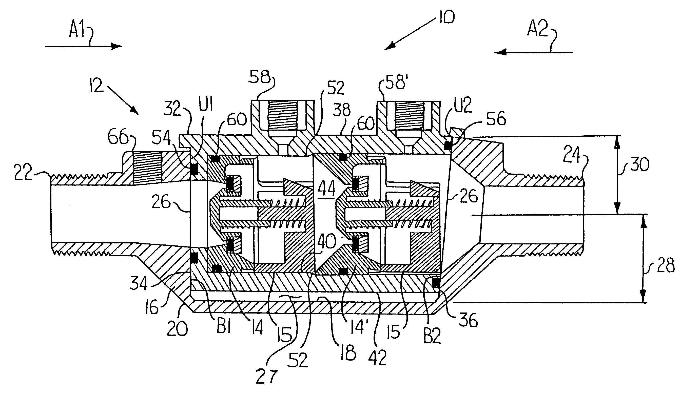
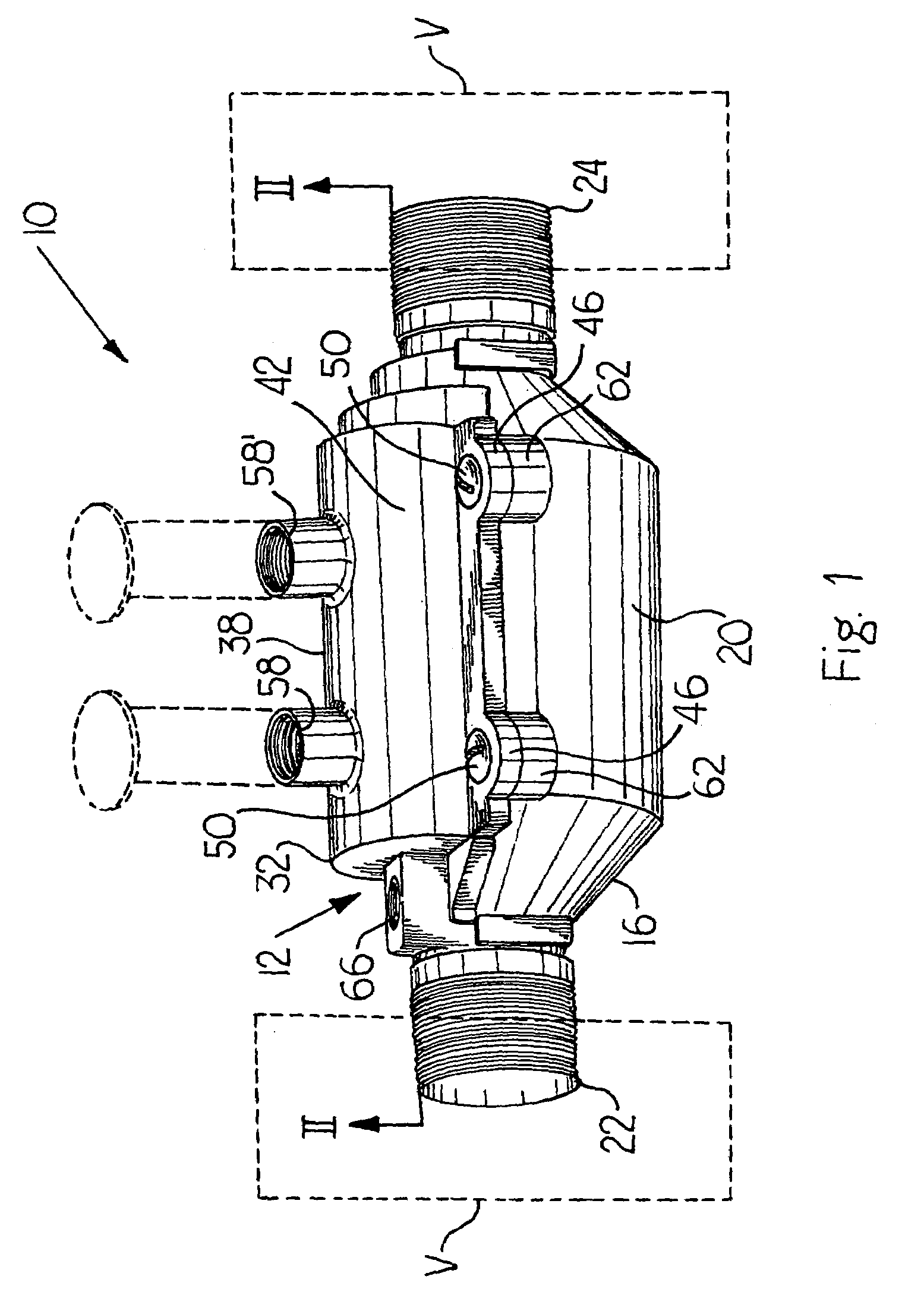
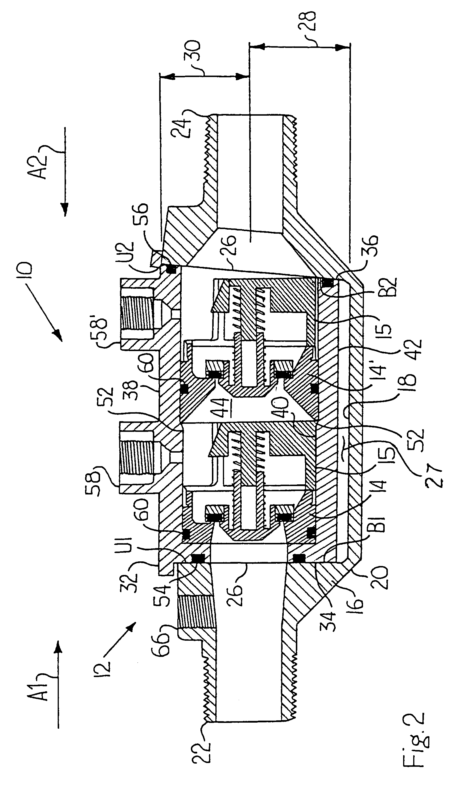
[0020]FIG. 1 shows a check valve arrangement 10 made in accordance with the present invention. The arrangement 10 includes a modular fluid casing 12 having one or more in-line check valves (and preferably two check valves 14, 14′ as shown in FIG. 2) received within the modular casing 12. Referring to FIGS. 2 and 3, the modular casing 12 includes a housing or receiving member 16 having an inner surface 18 and an outer surface 20 and a one-piece modular cage 32 having a first open end 34 and a second open end 36 removably seated within the housing 16. The housing 16 includes an inlet end 22 and an outlet end 24, wherein the inner surface 18 defines a flow channel 26 or modular cage receiving area 27 between the inlet end 22 and the outlet end 24 of the housing 16. The flow channel 26 is in fluid communication with the inlet end 22 and outlet end 24 of the housing 16 as shown in FIG. 3. The modular cage 32 includes a body 38 having an interior surface 40 and an exterior surface 42, whe...


PUM


Abstract

A double check valve that generally includes a modular fluid casing having a main housing, a one-piece modular cage, and at least one in-line check valve removably housed in the modular cage.

Description

CROSS REFERENCE TO RELATED APPLICATION[0001]This application claims the benefit of U.S. Provisional Patent Application No. 60 / 420,698, filed Oct. 23, 2002, entitled “Double Check Valve Assembly” which is hereby incorporated by reference in its entirety.BACKGROUND OF THE INVENTION[0002]1. Field of the Invention[0003]The present invention relates to check valve assemblies and, more particularly, to a modular fluid casing for a check valve.[0004]2. Description of Related Art[0005]Fluid valves generally include a main body having two ends. The main body also forms an internal flow cavity that fluidly connects the two ends and houses internal valves. In a typical installation, one end of the main body is connected to a fluid inlet pipe and the other end is connected to a fluid outlet pipe. Fluid flows from the fluid inlet pipe, through the internal flow cavity, is stopped, directed, or left unimpeded by the internal valves, and exits through the fluid outlet pipe. Such fluid valves can i...

Claims


Application Information

Patent Timeline
IPC IPC(8): F16K15/02F16K15/06F16K27/02
CPCF16K15/063F16K27/0209Y10T137/7504Y10T137/87917Y10T137/7838Y10T137/0491F16K15/066F16K2200/204
Inventor NOLL, BRAD L.KOCK, FRANKBEHNKE, CLARKVALDIVIA, SALVADOR
Owner ZURN INDS
Why Eureka
Try Eureka